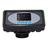
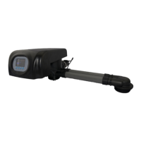
MODEL: N74A1-63510/N74A3-63610/N74B1-63510B/N74B3-63610B
24
Note: Use Interlock Cable to connect CN8 to CN7 on next valve in the loop.
One system with several valves, if interlock cable is disconnected, the
system is divided into two individual system.
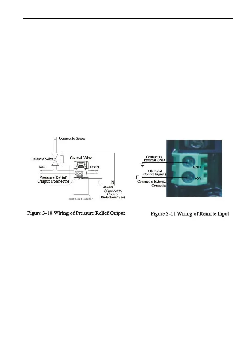
C. Pressure Relief Output
Runxin valve will cut off feeding water to drain line when it switches in
regeneration cycles. Thus in some water treatment system, e.g. Deep Well,
one booster pump was installed on the inlet to increase the system water
feeding pressure, this cut-off will cause pressure on inlet rising too fast to
damage the valve. Pressure Relief Output can be used to avoid this
problem. The wiring refer to Figure 3-10.
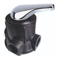
D. Remote Handling Connector
Online TDS meter monitors treated water other than a flow meter, or
PLC controls the regeneration time. When the controller receives a contact
closure from above instruments, regeneration begins. The wiring refers to
Figure3-11.
E. Interlock System
2 or more than 2 valves are interlocked connecting in one system and
all valves are in service but regenerate individually. The wiring refer to
Figure3-12.