HEAVY DUTY
SOD CUTTER
31
ADJUSTING PRESSURE PLATE CLEARANCE
9. From the right side of the unit, loosen the
adjusting nut until he cam can be rocked back
and forth approximately 1/4" (6.4mm). Be sure to
raise the trigger to ensure complete movement.
Trigger must NOT interfere with cam stop.
(Figure 3)
10. Install brass plugs and set screws into adjusting
nut and tighten set screws. Re-check the 1/4"
(6.4mm) rocking dimension. If necessary, loosen
the set screws, re-adjust nut, and re-tighten set
screws.
11. After cam movement is adjusted properly, install
the trigger spring, cut-off ram springs, dog wheel
assembly and chain guards.
12. Lubricate all ttings in the cut-off before operating
unit.
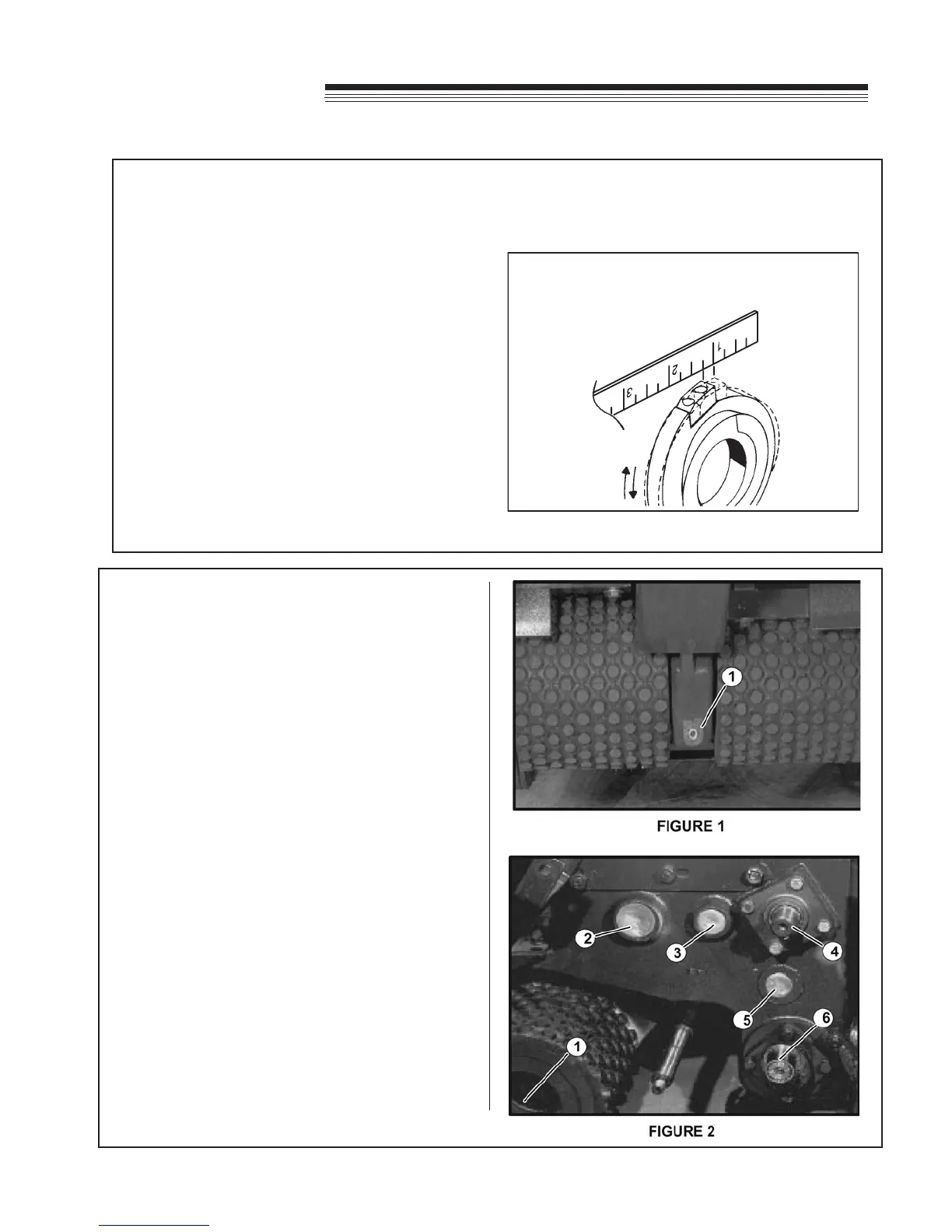
GEAR REPLACEMENT
1. Remove drain plug from front of gear case and
drain gear case. Remove gear case cover.
(Figure 1)
2. Remove belt shield and belt (if unit has cut-off,
remove cut-off chain and dog wheel assembly).
3. Remove screw, lockwasher, and atwasher from
end of belt pulley (if unit has cut-off, remove the
chain sprocket bolted to the belt pulley).
BE SURE
TRIGGER DOES
NOT INTERFERE WITH
CAM MOVEMENT
FIGURE 3
13. After assembly, refer to "Checking Brake
Clearance" and follow instructions accordingly.
GEAR SHAFT LOCATIONS: (Figure 2)
1. Drive wheel Chain Sprocket Shaft
2. Gear and Upper Chain Sprocket Shaft
3. Sliding Gear Shaft
4. Pulley Shaft
5. Idler Gear Shaft
6 Drive Gear Shaft
MAINTENANCE / SERVICE