8 MINI CRIMPER SERIES OPERATION MANUAL
0
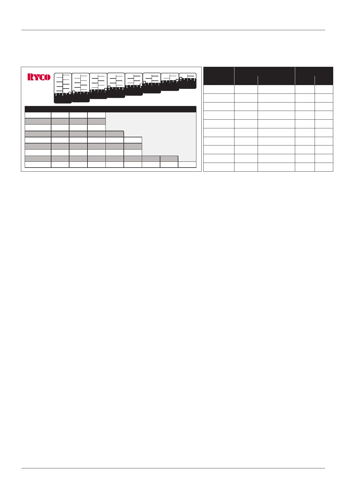
0 turn 1 turn 2 turn 3 turn 4 turn 5 turn 6 turn 7 turn
16-10
10 11 12
16-12
12 13 14
16-14
14 15 16
16-16
16 17 18 19
16-19
19 20 21 22 23
16-23
23 24 25 26 27
16-27
27 28 29 30 31
16-31
31 32 33 34 35 36 37
16-37
37 38 39 40 41 42 43 44
USE NEXT SIZE
DIE SET
8
6
4
2
7
5
3
1
0
0
8
6
4
2
7
5
3
0
8
6
4
7
5
3
0
2
1
8
6
4
7
5
3
8
6
7
5
0
4
8
6
7
0
8
7
0
5
6
8
0
7
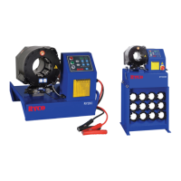
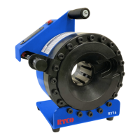
RY16 MINI CRIMPER
1. Select relevant die set and install into crimper.
2. Ensure that all dies are correctly installed in the crimper
3. Press red test button to ensure LED crimp light illuminates.
4. When the die set is inserted in the machine and the crimping measurement set, place the hose and coupling
assembly between the dies.
NOTE: For clearance and performance reasons, RYCO recommends crimping be performed with the
coupling positioned with its termination/connecting end protruding out of the front of the crimper.
5. Pressurise the RYCO hand pump (see page 10 for detailed pump instructions) or activate the air/hydraulic foot
valve to commence crimping the coupling.
6. The crimping diameter is reached when the red LED crimp light is illuminated.
7. Remove the hose assembly from the crimper after depressurising the hand pump or hydraulic foot pump (see
page 10 for detailed pump instructions).
8. Ensure that the crimp dimension is correct and make adjustments if necessary.
Operating the RY16
Changing the Die Set on RY16
1. Retract the crimper completely by depressing the hand pump or foot valve.
2. Isolate the airline from the foot valve to ensure the crimper cannot be activated.
3. Remove each crimp die segment by turning it in either direction or pulling it towards the centre of the crimper.
4. Ensure crimper master dies surfaces are clean and free of any debris.
5. Ensure that the die set to be installed are clean, undamaged and that all are marked with the same number.
6. With the die marking numbers facing the front of the crimper, insert each die so that the die pin engages with the
mating die pin hole in the crimper master die.
7. Ensure that all dies are correctly inserted in the machine.
Maintenance
The machine should be cleaned and lubricated every eight (8) operation hours. Retract the dies to lubricate. Use a
small brush to lubricate the cone shaped surfaces in the cylinder. Lubricate sparingly and often. Without lubrication, the
machine loses power and you will damage the sliding surfaces.
Refer to preventative maintenance section for maintenance requirements.
OPERATION
CRIMPING RANGE DIE LENGTH
Die Set
mm inch mm inch
RY16-07 7-10 0.276-0.394 60 2.36
RY16-10 10-12 0.394-0.472 60 2.36
RY16-12 12-14 0.472-0.551 60 2.36
RY16-14 14-16 0.551-0.630 60 2.36
RY16-16 16-19 0.630-0.748 60 2.36
RY16-19 19-23 0.748-0.905 60 2.36
RY16-23 23-27 0.905-1.062 60 2.36
RY16-27 27-31 1.062-1.220 60 2.36
RY16-31 31-37 1.220-1.457 60 2.36
RY16-37 37-44 1.457-1.772 60 2.36
Figure 4: Die Size and Crimp Range Chart
Crimp Range Chart



 To Next Page