HYDROSTATIC POWER TRAIN REPAIR
6 - 44 2/12/97
6. Measure brake components individually.
7. Replace components as necessary and as a set
only. Set brake assembly components aside for
final assembly.
Specifications:
Brake Components Wear Tolerances—
(G) brake puck (minimum) . . . . . . . 8 mm (0.3 in.)
(H) brake lever (minimum). . . . . . . 25 mm (1.0 in.)
(I) brake disc (minimum) . . . . . . 2.5 mm (.098 in.)
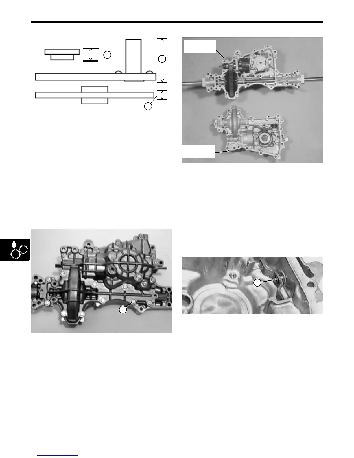
Separate Transaxle Housing Case Halves—
1. Remove seventeen transaxle housing cap screws
(B).
G
H
I
A
2. Carefully separate transaxle housing into upper and
lower case halves.
3. Remove any gasket residue from both case halves.
4. Inspect overall condition of components without
removing any of them. Visually target worn or
damaged parts for replacement.
5. Remove any remaining oil without removing any
components.
Disassemble Transport (Free-Wheeling) Assembly–
NOTE: Inspect transport actuating bracket and pin
assembly (A) for wear or leakage to outside. If
assembly is in good condition, just set lower
case half aside for final assembly.
Lower Case
Half
Upper Case
Half
A
www.servicemanualall.com
 Loading...