DIAGNOSTICS ELECTRICAL
3/5/97 4 - 9
DIAGNOSTICS
CRANKING & FUEL SHUTOFF
SOLENOID CIRCUIT OPERATION
Function:
The cranking system is used to energize the starting
motor.
Operating Conditions:
In order to crank the engine; the blade drive lever must
be disengaged (blade switch plunger depressed), the
brake pedal must be depressed (brake switch plunger
depressed), and the ignition switch must be in the start
position. The operator does not have to be on the seat
to crank the engine if the above conditions are met.
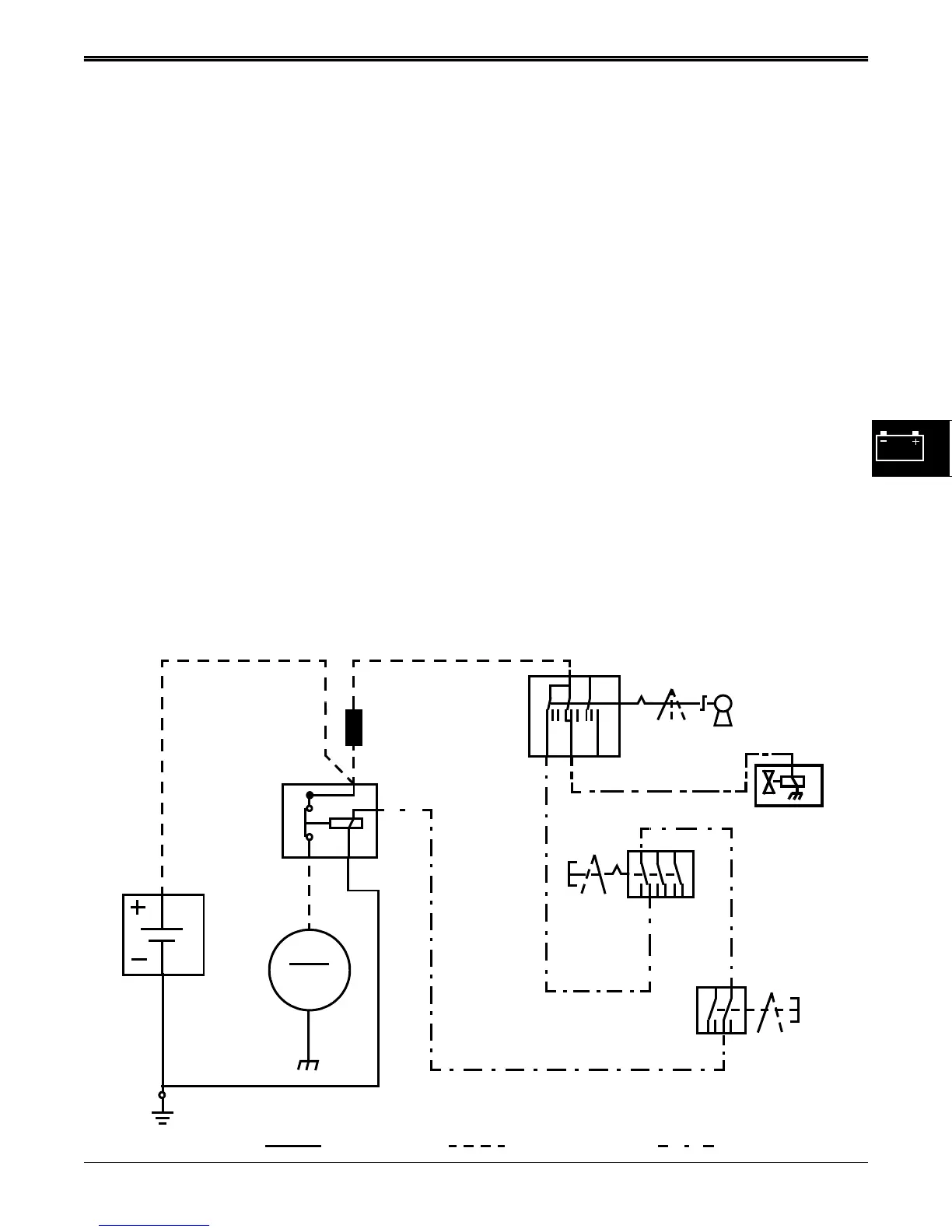
Theory of Operation:
The starting motor has a separate starter solenoid,
located under the operator’s seat. Current flows from
the battery positive terminal to the starter solenoid
secondary terminal, plug in fuse, and ignition switch.
With the ignition switch in the start position, current
flows from the ignition switch, to the blade drive switch,
brake switch, and to the starter solenoid primary
terminal, energizing the pull-in windings of the solenoid
and engaging the starter.
The 16 HP fuel shut-off solenoid is also energized by
the ignition switch and allows fuel to flow to the
carburetor.
The blade drive switch is located under the left side of
the mower frame, at the end of the blade drive lever
shaft. It is used to prevent the engine from cranking if
the blade drive is engaged. With the blade drive lever
disengaged, (blade drive switch plunger depressed),
current flows through the 705 Pur/Wht wire to the brake
switch.
The brake switch is located under the right side of the
mower frame, in front of the brake pedal bell crank.
When the park brake is engaged, the bell crank
depresses the brake switch plunger and the switch is
closed, energizing the starter solenoid primary coil.
The starter solenoid plunger is pulled in by the primary
coil, closing the secondary terminals and supplying
high battery current to the starter motor. The spinning
of the starter motor extends the starter bendix drive
into the engine flywheel, turning over the engine until
the ignition circuit fires.
Once the engine starts, the operator releases the
ignition switch to run position. The current flow to the
starter solenoid primary coil is stopped, releasing the
starter solenoid plunger, and cutting off the high battery
current to the starter motor.
1
0
012
1
M
105 BLK
201 RED
200 RED
BLK
RED
710 PUR
700 PUR
STARTER
MOTOR
STARTER
SOLENOID
FRAME GROUND
BATTERY
705 PUR/WHT
IGNITION
BLADE
DRIVE
BRAKE
SWITCH
GROUND POWER CONTROL
0=OFF
1=RUN
2=START
0=OFF
1=ON
0=OFF
1=ON
0
FUEL
SHUT-OFF
SOLENOID
401 YEL
SWITCH
PLUG-IN
FUSE
SWITCH
www.servicemanualall.com
 Loading...