GEAR POWER TRAIN REPAIR
5 - 22 2/12/97
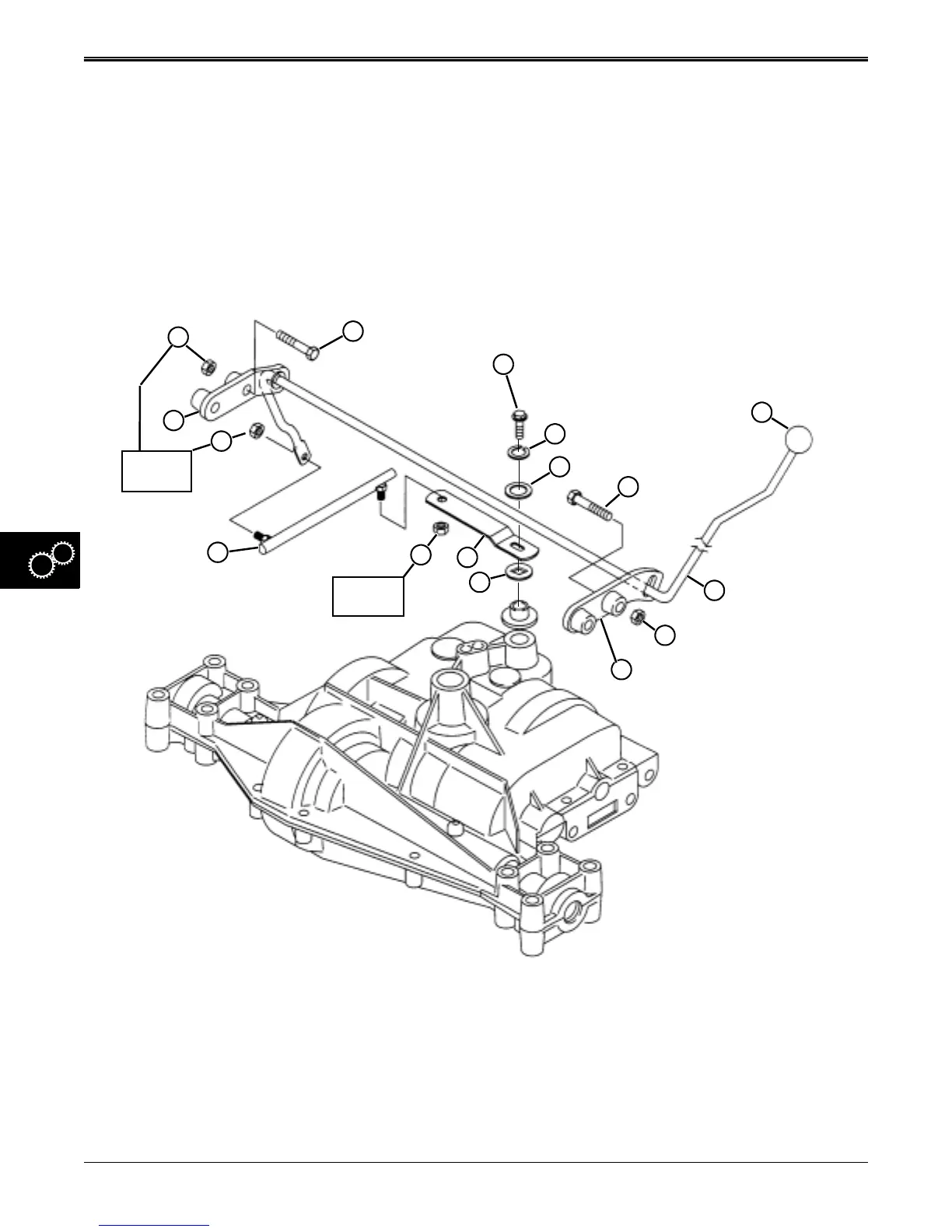
SHIFT LINKAGE REMOVAL &
INSTALLATION
1. Remove battery.
2. Block rear of tractor off ground. Remove left drive
wheel.
3. Remove shift knob (G).
4. Remove lock nuts (M and O) to remove shift link
(N).
5. Remove lock nuts (A and I) and cap screws (B and
F).
A–Lock Nut G–Shifter Knob M–Lock Nut
B–Cap Screw H–Shift Rod N–Shift Link
C–Shift Lever Cap Screw I–Lock Nut O–Lock Nut
D–Lock Washer J–Right-Hand Bracket P–Left-Hand Bracket
E–Washer K–Special Square-Hole Washer
F–Cap Screw L–Shift Lever
A
B
C
D
E
N
M
L
K
F
I
H
G
16 N•m
(12 lb-ft.)
15 N•m
(11 lb-ft.)
15 N•m
(11 lb-ft.)
J
15 N•m
(11 lb-ft.)
P
O
6. Adjust mounting brackets (J and P) so shift rod (H)
can be removed from the left side of the frame. You
will have to “snake” the shift rod from the tractor.
7. Remove cap screw (C) to remove shift lever (L) and
washers (D, E, and K).
8. Replace necessary components.
9. Install shift linkage in reverse order of removal.
10. Tighten shift lever cap screw and lock nuts to
specifications shown.
www.servicemanualall.com
 Loading...