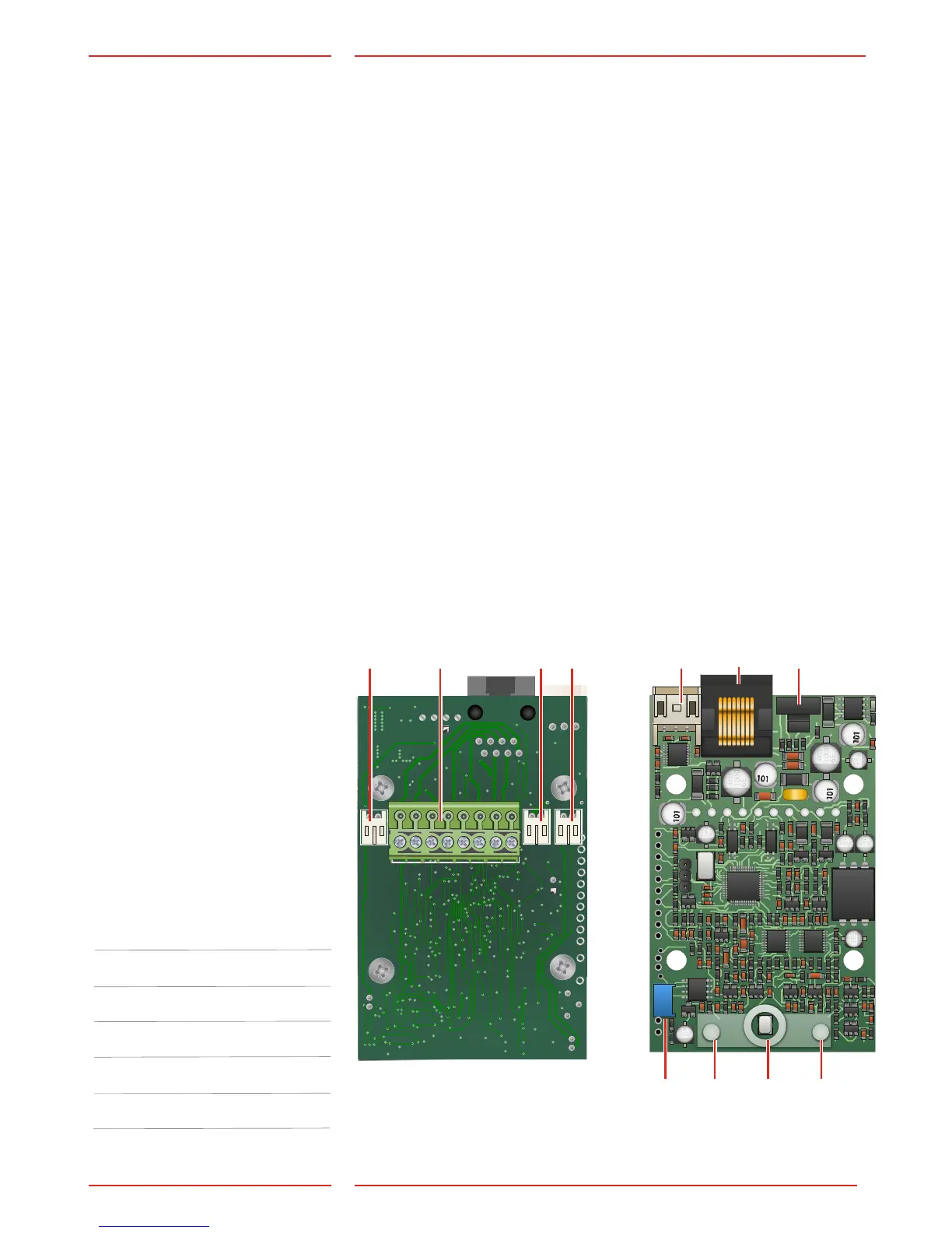
Local button*
Only N/O.
Connected with *Cable13.
Screw connector terminals*
Emergency light*
Is connected with *Cable13.
Hearing loop*
Is connected with *Cable13.
RS232 PC connection
For rmware update.
Terminal RJ45
Input/output, bus connection,
power and external pictogram.
Address selector
Selects the bus address for the
unit.
Volume control
Pictogram yellow
Microphone
Pictogram green
* Note: This connection may
not be present depending
on your product.
Change the default address
settings using SafeLine Pro
or SafeLine CONNECT.
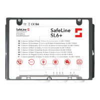
Overview SL6+
voice station
Address Unit
1 Car unit
2 Top unit
3 Lift pit unit
4 Fire unit
5 Fire unit
6 Fire unit
Default address setting:
1.
2.
3.
4.
5.
6.
7.
8.
9.
11.
10.