FP5/GP5 User’s Manual 49
3.2 PARAMETER SET-UP & INITIALIZATION
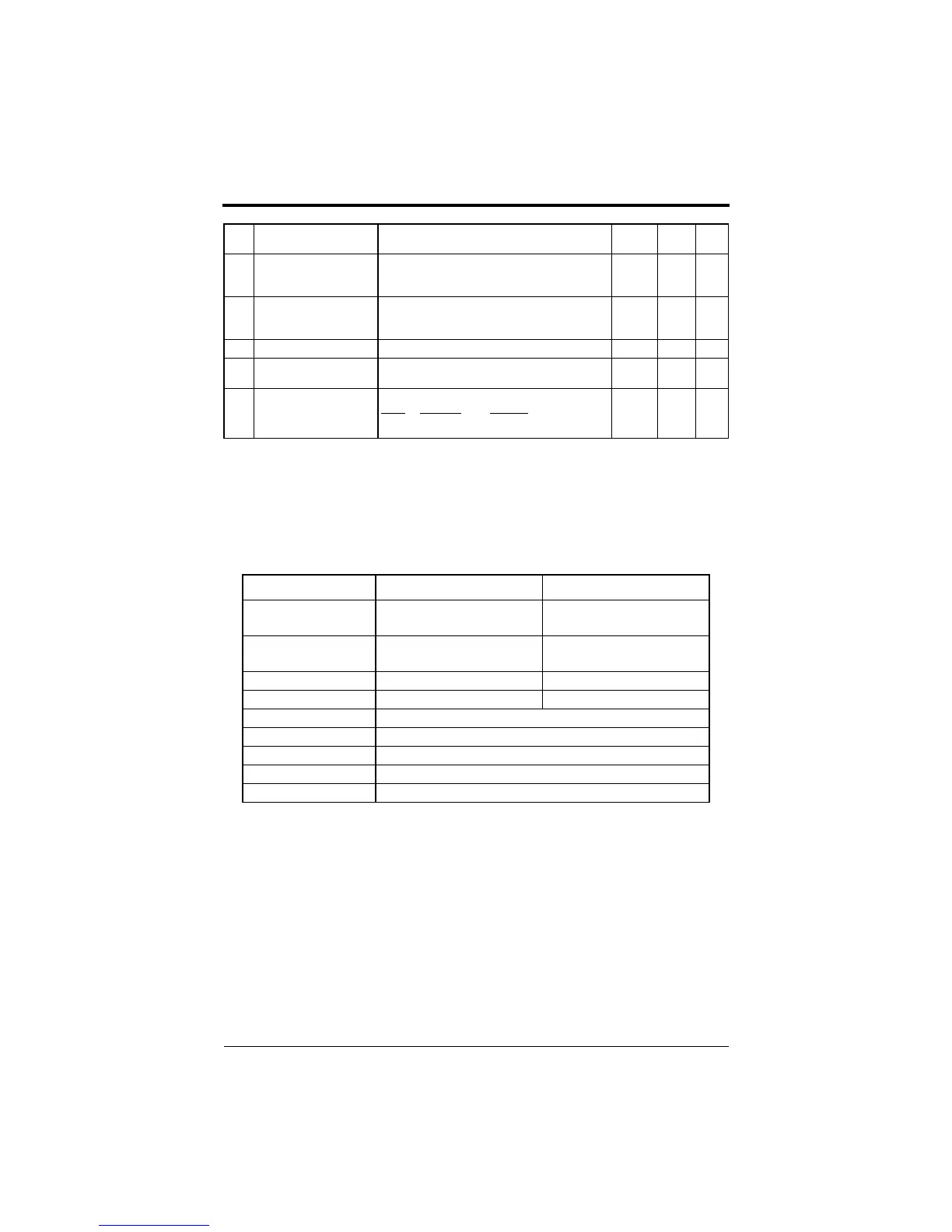
Parameter Selection/Initialization (n001, Password)
The following table describes data which can be set or read when parame-
ter n001 is set.
n112Low frequency OL start
point
(Low Freq OL2 Start)
Unit: 0.1Hz
Setting range: 0.0 ~ 10.0Hz
6.0Hz -
n1130Hz continuous operation
level
(OL2_Level_@_0 Hz)
Unit: 1%
Setting range: 25 ~ 100%
50% -
n114Not used
- - - -
n115kVA selection
(Inverter kVA Sel)
Unit: 1
Setting range: PC5 (0~8, 20~29), P5(9~F, 2A~35)
kVA
Dependent
-
n116CT / VT selection
(CT / VT Selection)
LED
Setting
LCD Setting Description
0: CT Operation Constant torque
1: VT Operation Variable torque
- 7,9
Setting Parameters that can be set Parameters that can be viewed
0
(parameter read-only)
n001 n001 to n116
1
(factory default)
n001 to n035 n001 to n116
2 n001 to n053 n001 to n116
3 n001 to n116 n001 to n116
4, 5 Not used
6 Initialize: 2-wire sequence (Japanese specifications)
7 Initialize: 3-wire sequence (Japanese specifications)
8 Initialize: 2-wire sequence (American specifications)
9 Initialize: 3-wire sequence (American specifications)
No. Function Name
(LCD Operator Display)
Description Factory
Default
User
Setting
Ref.
Page
Chapter 3 - Programming Features
FP5/GP5 Operation
efesotomasyon.com - Control Techniques,emerson,saftronics -ac drive-servo motor