FP5/GP5 User’s Manual 73
Chapter 3 - Programming Features
FP5/GP5 Operation
Torque Detection
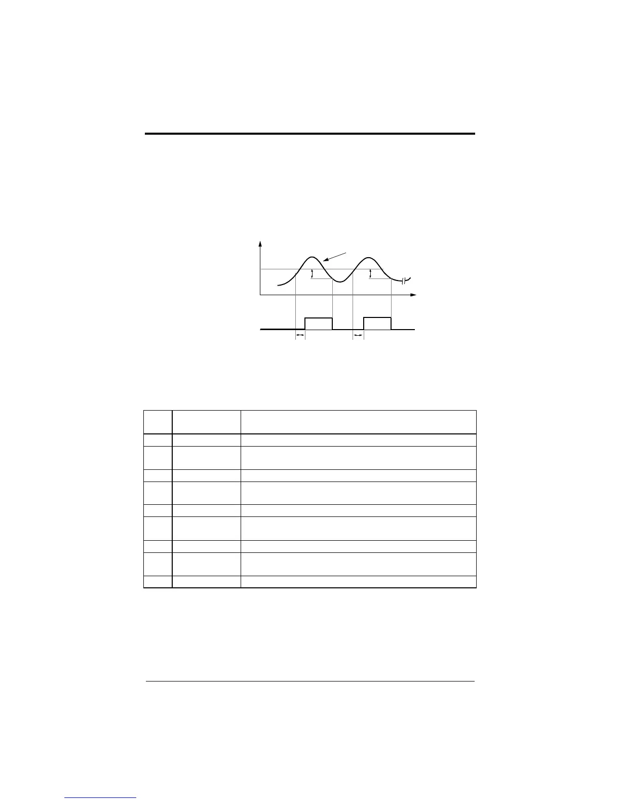
The over/undertorque detection circuit will activate when the motor load
causes the motor current to go above or below torque detection level (n078)
respectively. When the over/undertorque condition is detected, alarm sig-
nals are sent to multi-function output terminals MA, MB and/or M1.
To output an over/undertorque detection signal, set multi-function contact
output selection n041 or n042 to “6” (N.O. contact) or “7” (N.C. contact).
·Over/undertorque Detection Function Selection (n077, Torq Det Sel)
Notes:
·To detect torque during acceleration or deceleration, select a setting that contains
“RUN”.
·To continue operation after over/undertorque detection, select a setting that contains
“Alm”. During detection, the digital operator displays “oL3” alarm (blinking).
·To stop the inverter after an over/undertorque detection fault, select a setting that
contains “Flt”. During detection, the digital operator displays “oL3” fault.
LED
Setting
LCD Setting Description
0 Disabled Detection disabled (factory default)
1 OT/SpdAgree/Alm
Overtorque detection begins at speed agree; continue running after
detection. (Alarm)
2 OT/Run/Alm Overtorque detection at run; continue running after detection. (Alarm)
3 OT/SpdAgree/Flt
Overtorque detection begins at speed agree; coast to stop after detec-
tion. (Fault)
4 OT/Run/Flt Overtorque detection at run; coasts to stop after detection. (Fault)
5 UT/SpdAgree/Alm
Undertorque detection begins at speed agree; continue running after
detection. (Alarm)
6 UT/Run/Alm Undertorque detection at run; continue running after detection. (Alarm)
7 UT/SpdAgree/Flt
Undertorque detection begins at speed agree; coast to stop after
detection. (Fault)
8 UT/Run/Flt Undertorque detection at run; coast to stop after detection. (Fault)
* Release width (hysteresis) during overtorque detection is 5% of the inverter rated current level.
Inverter Rated Current
n078
Time
ON ON
n079 n079
Multi-function Contact
Output Signal
(Overtorque Detection Signal)
Terminal MA, MB, M1
**
Figure 43 Torque Characteristics
Motor Current
efesotomasyon.com - Control Techniques,emerson,saftronics -ac drive-servo motor