94 FP5/GP5 User’s Manual
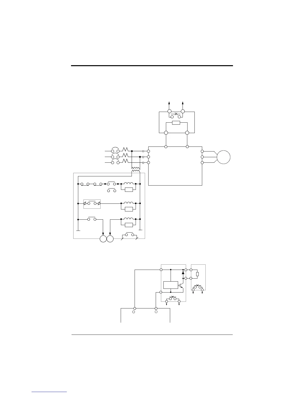
A-1 BRAKING CONNECTION DIAGRAMS
Braking Resistor Unit
230V: 5~25HP
460V: 5~25HP
P B
1
2
Overload Relay Trip Contact
Braking Resistor Unit
Overload Relay Trip Contact
of Braking Resistor Unit
1 2
MC
Fault Contact
TRX
SA
TRX
THRX
SA
SA
MC
MC
THRX
ON
OFF
MA
MC
VS-616PC5
L1
L2
L3
T1
T2
T3
L1
L2
L3
MCCB
MC
B1 B2
M
Figure 53 External Control Circuit for FP5/GP5 Braking Resistor Connection
230V: 20~25HP
Figure 54 External Control Circuit for FP5/GP5 Braking Unit Connection ( CDBR Type)
Braking Unit
Braking Resistor
Level
P0
P
B
B
1
2
P
Unit
3
4
N
Detection
Overload Relay Trip Contact
-
+
3
3 & 4 output signal to
multi-function fault input.
Appendix A-1
Braking Connection Diagrams
efesotomasyon.com - Control Techniques,emerson,saftronics -ac drive-servo motor