Suntrio Plus Series
-32-
Chapter 6 Debugging Instructions
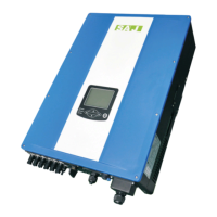
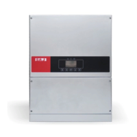
6.1 Introduction of Human-computer Interface
Figure 6.1 Human-computer Interface
Object Description
A
Communication light: blue light flashing = receiving data
yellow light flashes = sending data
B
Status indicator lamp: Red LED light = Fault; Green LED light = operation;
when red and green light are all off, the inverter is in initializing state or
countdown for grid-tie.
C
Power indicator light: yellow light: the power system of inverter is operating
normally
D◀
Moves the cursor or the focus point to the left
E ▶
Moves the cursor or the focus point to the right
F(ENT) Starts the menu / button to confirm selection
G
▲
Moves the cursor up or increases the setting value
H
▼
Moves the cursor down or reduces the setting value
The inverter provides five buttons for inquiry of operational information and
parameters, these five buttons can be used repeatedly.
 Loading...