44
and the acoustic alarm will beep every 5 sec. Next the following
message will be displayed in the LCD panel:
LANGUAGE
AAAAAA
... where AAAAAA corresponds to the language of the menus
displayed in the LCD panel. The available languages are: English,
Spanish, French, German, Turkish and Russian.
By means of the keys () and (), move till selecting the lan-
guage and validate with (ENT). Since this moment, the screens
will be displayed in the set language (in this case English).
The screen to set the time (hour, minutes, seconds) and date (day
of the week, day of the month, month and year) will be displayed.
Clock: HH:MM:SS
Date: WKD DD/MM/YYYY
To begin the time and date setting press (ENT). Each character
that has a value, it is modified one by one, to change the first
character of the field use the keys () and () and validate
with (ENT). To jump to the next character use the keys () and
(). To finish press (ESC), the values will be validated and the
following screen is displayed.
UNIT NOMINAL VOLTAGE
3 X AAA V
... where AAA corresponds to the nominal phase to phase
value, of the operating voltage of the equipment.
By means of the keys () and (), move it till the nominal
value of the power supply voltage and validate it with (ENT).
When the wished value is not in the chart 4, select the
closest one and validate with (ENT).
Type of voltage interval Value of phase to phase voltage
LV (Low voltage),
Referred to the model
3x200 V / 3x208 V / 3x220 V /
3x230V
HV (High voltage) 3x380 V / 3x400 V / 3x415 V
Table 4. Nominal values, operating voltages of the equipment.
Once the operating voltage is selected, it is compulsory to se-
lect the nominal frequency. The following message is displayed:
NOMINAL FREQUENCY
AAAA
By means of the keys () and (), move till one of the fol-
lowing frequency values and validate with (ENT):
– 50 Hz: Frequency of the equipment (rectifier and in-
verter), will be set to 50 Hz.
– 60 Hz: Frequency of the unit (rectifier and inverter), will
be set to 60 Hz.
– AUTO: In each UPS start up, the input frequency will be
sensed and set to 50 or 60 Hz accordingly.
This setting is not recommended if the unit is
supplied by a generator set.
Once the operating frequency is selected, the following mes-
sage will be displayed:
CONFIG. COMPLETED ?
<ENT> YES <ESC> NO
Press the (ENT) key to validate the values, the acoustic alarm
will be stopped.
Press (ESC) to go back to the start of the installation menu to
set them again.
Once they are validated, it will not be possible to set
them again, being necessary the T.S.S. intervention.
Omit the possible wrong rotation alarm triggering that could
arise during the procedure over an equipment, because it
will be treated in section 6.2.2.2.
Continue with the described procedure in the next section,
considering that the stated actions in the first three steps
are already done.
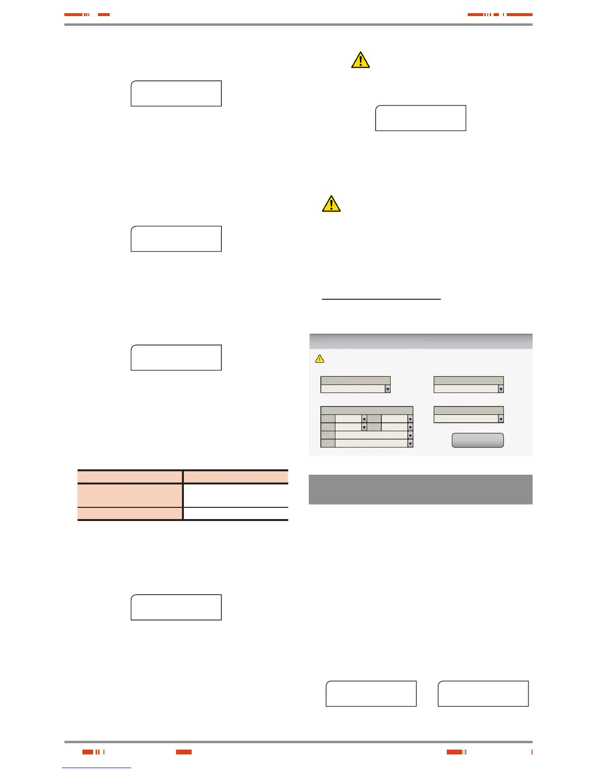
• In equipments with touchscreen, the installation menu will be
displayed in a single screen with all the parameters to select. Pro-
ceed according to section 1 of the EL064*01 document.
Welcome to the configuration menu
CONFIRM
Choose Language
Unit Nominal Voltage
Nominal Frequency
Time & Date
Hour
Minute
Mont
h
Week
Day
Day
Year
Please set all parameters bellow and then confirm to exit this menu.
English
3 x AAA V
AA Hz
**
**
**
****
**********
**********
6.2.2.2. Daily start up procedure, for equipments with
alphanumerical display.
When coming from the previous section the first three steps will be
skipped, because they are already done in the first commissioning.
For the daily start up procedure, starting from equipment/s shutdown
completely, make all the next stated actions:
• Supply input voltage to the switchgear panel board.
• Turn «On» the input switch or switches of the panel board, de-
pending if it is a single equipment or parallel system.
• Turn the UPS or each UPS input switch (Q1a) to «On» position.
• The LCD of the Control Panel (PC) of each equipment will be
turned on automatically.
For single equipments the LCD panel will display the left mes-
sage of the screen 0.0 and for parallel systems both messages
will be displayed 0.0 :
SLC CUBE 3+
11:19:35 11/09/2013
screen 0.0
Paral. 002 Out. SW=OFF
11:19:35 11/09/2013
screen 0.0
Ì
É
USER MANUAL