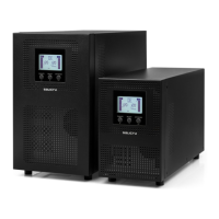
22
(1): (a) (b) (c) (d) (e)
(2) (3)
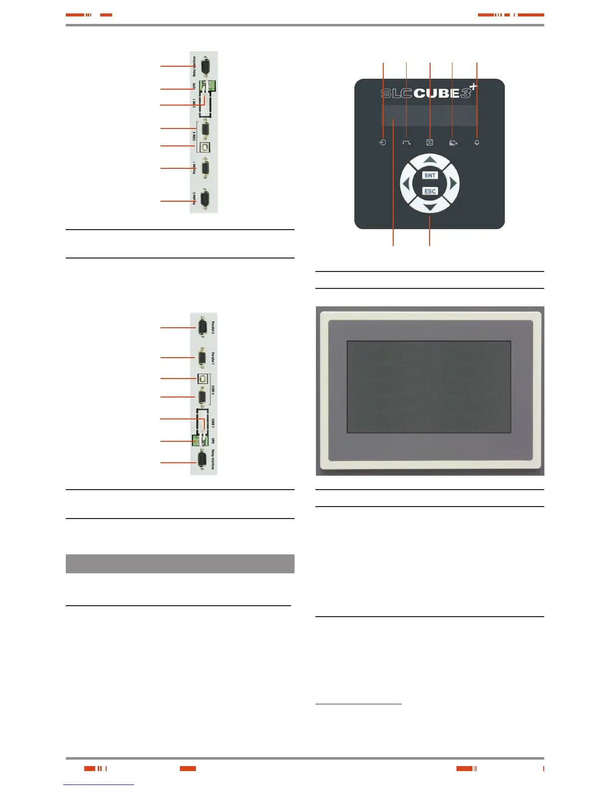
(X32)
(X50)
(PT
2
)
(X31)
(X31
USB
)
(X36
i
)
(X36
o
)
(X36
o
)
(X36
i
)
(X31
USB
)
(X31)
(PT
2
)
(X50)
(X32)
Fig. 21. Connection of communications for models up to 60 kVA
(LV) / 120 kVA (HV).
Fig. 22. Connection of communications for models higher than 60
kVA (LV) / 120 kVA (HV).
Fig. 23. Alphanumerical control panel (see section 7).
Fig. 24. Touchscreen control panel (see EL064*01 user's manual).
4.1.2 Legend corresponding to the equipment views.
Protection and manoeuvring parts (Q*) in the UPS cabinet:
(Q1a) Input circuit breaker or switch according to the equipment
power rate.
(Q2) Output switch.
(Q3) Battery fuse holder switch with 3 fuses in models up to 20
kVA (LV) / 40 kVA (HV) or switch in models with higher power
rate and/or B1 versions.
(F3) Battery fuse holder switch with 3 fuses. Up to 20 kVA (LV) /
40 kVA (HV) models with extended back up time, where the
batteries are fitted in or ready to be fitted in part inside the own
UPS cabinet.
(Q4a) Static bypass switch, two or three poles depending on
the mains typology (-B version only).
(Q5) Manual bypass switch.
Protection and manoeuvring parts(Q*) in the battery cabinet:
(Q8) Battery fuse holder switch of 3 fuses, for models up to 60
kVA (LV) / 120 kVA (HV).
Battery switch, in models higher than 60 kVA (LV) / 120 kVA
(HV). Also there are 3 fuses (F8) with no switch function,
located inside the cabinet.
Connection parts (X*):
(X1) Terminal of input phase R.
(X2) Terminal of input phase S.
(X3) Terminal of input phase T.
USER MANUAL