12
Fig. 21
(SL)
(BL)
(t
2
)
(1)
(Q4a)
(Q1a)
(TB)
(t
1
)
(X1)
(X5)
(X2)
(X3)
(X4)
(1)
(X14)
(1)
(X15)
(1)
(X16)
(1)
(X17)
(PR)
(Q5)
(Q2)
(Q3)
(F3)
(3)
(X11)
(2)
(X23)
(2)
(X12)
(2)
(X10)
(X34)
(X45)
(PT
1
)
(X51)
(X34
ETH
)
(X9)
(X8)
(X7)
(X6)
Fig. 21
(SL)
(BL)
(t
2
)
(1)
(Q4a)
(Q1a)
(TB)
(t
1
)
(X1)
(X5)
(X4)
(1)
(X14)
(1)
(X17)
(X6)
(X9)
(PR)
(Q5)
(Q2)
(Q3)
(F3)
(3)
(X11)
(2)
(X23)
(2)
(X12)
(2)
(X10)
(X34)
(X45)
(PT
1
)
(X51)
(X34
ETH
)
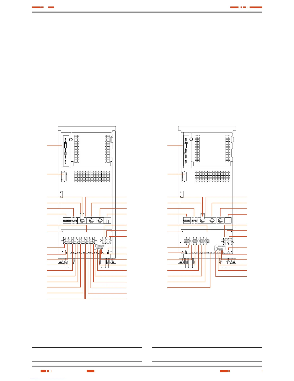
(1)
Equipments with separate static bypass line only (-B).
(2)
Equipments with extended back up time or 30 kVA (LV) / 60 kVA
(HV) power rates only.
(3)
Battery protection in equipments with extended back up time
only, where batteries are fitted in or ready to be fitted in part
inside the own UPS cabinet.
Fig. 6. UPS front view with door opened, 5 to 30 kVA (LV) /
7.5 to 60 kVA (HV) models and III / III setting.
(1)
Equipments with separate static bypass line only (-B).
(2)
Equipments with extended back up time or 30 kVA (LV) / 60 kVA
(HV) power rates only.
(3)
Battery protection in equipments with extended back up time
only, where batteries are fitted in or ready to be fitted in part
inside the own UPS cabinet.
Fig. 7. UPS front view with door opened, 5 to 30 kVA (LV) / 7.5
to 60 kVA (HV) models and II / II setting (L).
USER MANUAL