11
SALICRU
4. PRESENTATION.
4.1. VIEWS.
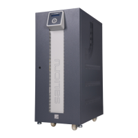
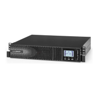
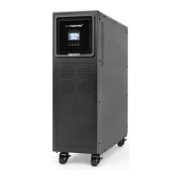
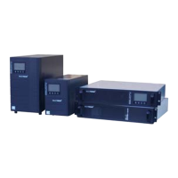
4.1.1. Views of the equipment.
Figures from 1 to 20 show the illustrations of the equipments ac-
cording to model, nominal operating voltage and input-output setting,
which is summarised in the chart 1.
Format of protections and size of the terminals shown in the figures
of this document, always correspond to the highest power rate model
manufactured in that cabinet, at the same power supply voltage and
input-output setting.
Nevertheless and as the product is in constant evolution, some dis-
crepancies or small contradictions can arise. So, if any questions, the
labels over the own equipment will prevail.
Each equipment model corresponds to one power rate,
voltage, frequency and input and output currents. All values
of these features can be checked in the nameplate, located at the
back of the front door (PF), and act in your installation accordingly.
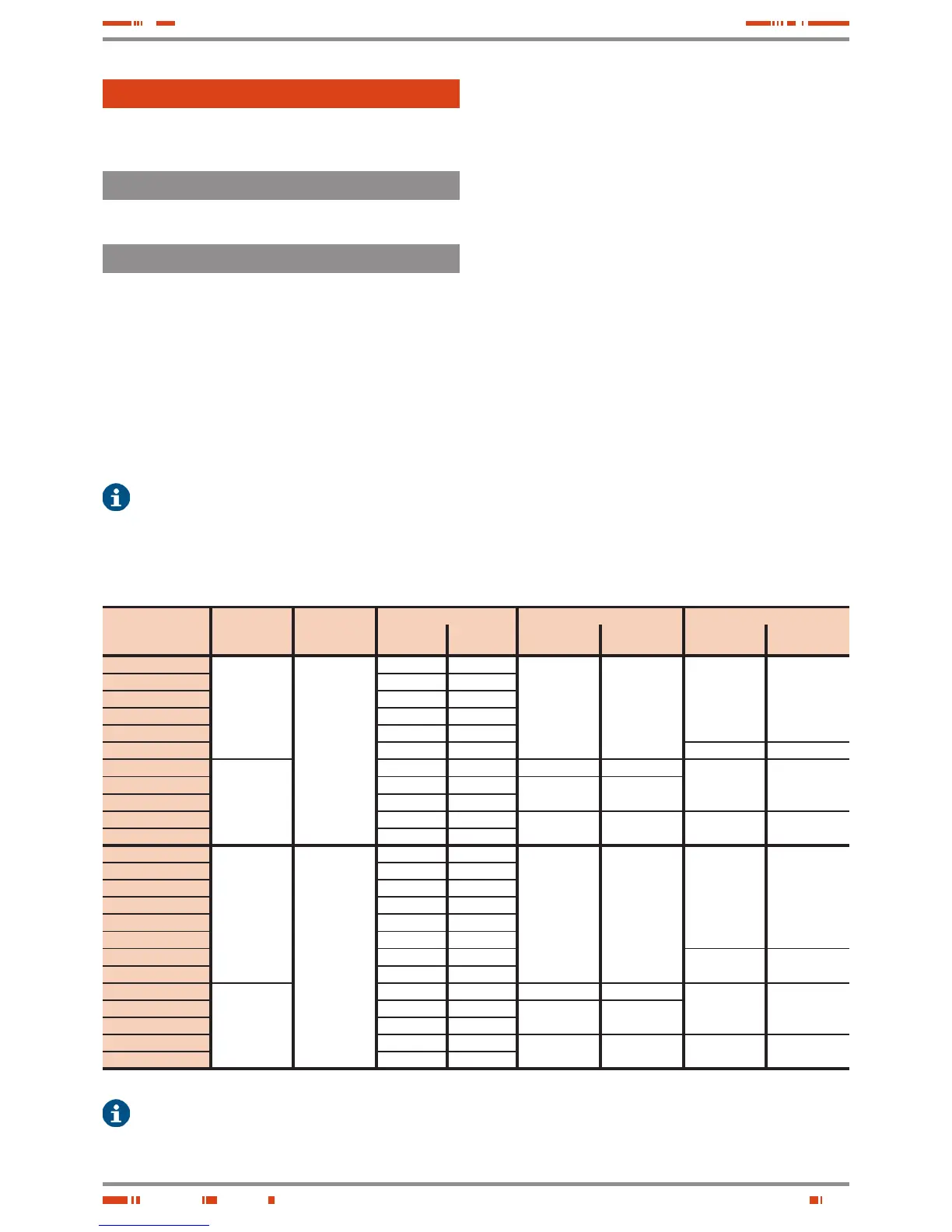
Model
Input - output
setting
Voltage (V)
Power (kVA / kW) Fig. nr. Front UPS cabinet Fig. nr. Front battery cabinet
Setting
III/III
Setting
L / M / N
Door closed Door opened Door closed Door opened
SLC-5-CUBE3+
No ref. : III / III
L : I / I
M : I / III
N : III / I
«LV»
3x200.. 3x230 V
(115.. 133 V in
single phase)
5 / 4,5 5 / 4
1 6 / 7 / 8 / 9
Battery cabinet
for extended
back up time
models only,
ver 15
Battery cabinet
for extended
back up time
models only,
ver 16
SLC-7,5-CUBE3+ 7,5 / 6,75 7,5 / 6
SLC-10-CUBE3+ 10 / 9 10 / 8
SLC-15-CUBE3+ 15 / 13,5 15 / 12
SLC-20-CUBE3+ 20 / 18 20 / 16
SLC-30-CUBE3+ 30 / 27 30 / 24 15 16
SLC-40-CUBE3+
Available at
setting III / III
only
40 / 36 40 / 32 2 10
17 18SLC-50-CUBE3+ 50 / 45 50 / 40
2
(*) 3 for (-B)
11
(*) 12 for (-B)
SLC-60-CUBE3+ 60 / 54 60 / 48
SLC-80-CUBE3+ 80 / 64 80 / 64
4
(*) 5 for (-B)
13
(*) 14 for (-B)
19 20
SLC-100-CUBE3+ 100 / 80 100 / 80
SLC-7,5-CUBE3+
No ref. : III / III
L : I / I
M : I / III
N : III / I
«HV»
3x380.. 3x415 V
(220.. 240 V in
single phase)
7,5 / 6,75 7,5 / 6
1 6 / 7 / 8 / 9
Battery cabinet
for extended
back up time
models only,
ver 15
Battery cabinet
for extended
back up time
models only,
ver 16
SLC-10-CUBE3+ 10 / 9 10 / 8
SLC-15-CUBE3+ 15 / 13,5 15 / 12
SLC-20-CUBE3+ 20 / 18 20 / 16
SLC-30-CUBE3+ 30 / 27 30 / 24
SLC-40-CUBE3+ 40 / 36 40 / 32
SLC-50-CUBE3+ 50 / 45 50 / 40
15 16
SLC-60-CUBE3+ 60 / 54 60 / 48
SLC-80-CUBE3+
Available at
setting III / III
only
80 / 72 80 / 64 2 10
17 18SLC-100-CUBE3+ 100 / 90 100 / 80
2
(*) 3 for (-B)
11
(*) 12 for (-B)
SLC-120-CUBE3+ 120 / 108 120 / 96
SLC-160-CUBE3+ 160 / 128 160 / 128
4
(*) 5 for (-B)
13
(*) 14 for (-B)
19 20
SLC-200-CUBE3+ 200 / 160 200 / 160
(*) The equipments with separate static Bypass line (-B), are supplied in the same cabinet as basic models, less those ones stated in this
chart with other Nr of Fig..
Tabla 1. Reference relation among models and illustration.
In the description of this manual, there are references to «LV» (Low
voltage) and «HV» (High voltage) abbreviations, described in the no-
menclature of the model with an «A» for «LV» and omitted for «HV»,
grouping the following interval of voltages:
• LV.- 3x200 to 3x230 V (115 to 133 V in single phase).
• HV.- 3x380 to 3x415 V (220 to 240 V in single phase).
These abbreviations do not have any other purpose than matching
and/or helping in order to give a better comprehension of the de-
tailed information in this document and even they are not shown
either in the nomenclature, or in the reference of the nameplate
model.
All models can operate as single units or connected in parallel with
other equipments of the same family, because the needed elec-
tronic kit is already included.
Parallel connection can be done at any time when the upgrading
requirements are needed to increase the supplied power of the
equipment or in order to have redundant operating systems for in-
stallations with higher safety.
Do not connect SLC CUBE3+ equipments of different features
versions, settings, back up times or duplicated addresses (i.e.: two
equipments, although they are identical, coming from two parallel
systems and with the same address) in parallel.
In any parallel system only one and different address is assigned to
each equipment that makes the system.