49
SALICRU
equipments in parallel, the hierarchy of «reserved by-
pass Slave» will be taken by the one with the highest
address among the «bypass Slave».
– «Paral. Mst. Volt» voltage Master of the parallel system.
By default, the first UPS on normal operating (inverter in
operation), that the output switch (Q2) is turned «On».
– «Paral. Slv. Vt.Rsv» reserved voltage Slave of the par-
allel system. Equipment on normal operating (inverter in
operation), that the output switch (Q2) is turned «On»
in 2nd place or subsequently (after the «Paral. Mst.
Volt» or «Paral. Mst. Vt.Rsv»). Initially, it corresponds to
the equipment with the highest address, excepting the one
from «Voltage Master». In case of failure of the Master,
it will take its functions.
– «Paral. Slv. Volt» voltage Slave of the parallel system
(systems with more than two equipments only). Equip-
ment on normal operating (inverter in operation), that
the output switch (Q2) is turned «On» in 2nd place or
subsequently (after the «Paral. Mst. Volt» or «Paral. Mst.
Vt.Rsv»). It will become as «reserved voltage Slave»,
when it practise as «voltage Master». In systems with
more than three equipments in parallel, the hierarchy of
«reserved voltage Slave» will be taken by the one with
the highest address among the «voltage Slave».
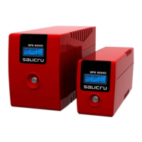
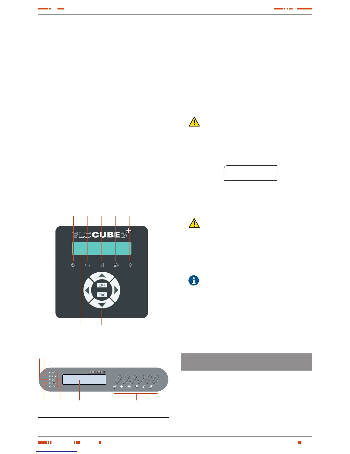
(1): (a) (b) (c) (d) (e)
(2) (3)
c b a
d e 1
2 3
Fig. 40. Indications of LED from control panel (PC).
• Turn «On» the output switch or switches of the panel board, de-
pending if it is single equipment or parallel system.
• Turn the output switch (Q2) of the UPS or each UPS «On».
The equipment or parallel system supplies voltage to the output
terminals of the switchgear panel board.
• Make sure that the inverter on LED indication (c) lights (green),
and bypass LED (b) is turned OFF in all UPSs (see Fig. 40).
If the status of the LEDs is wrong, please contact with the
S.T.S. (Service and Technical Support).
• For equipments with external battery cabinet, turn the switch-
fuse holder of the battery cabinet (Q8) of each UPS to position
«On».
DO NOT TRY to make this manoeuvre in any other
moment, since this operation could damage the
equipment and/or cause possible accidents.
• Once the rectifier is completely working, a process of equaliza-
tion (DC bus voltage starts to be equalized with battery voltage)
will be started. After a few seconds (depending on the battery
level), an alarm message like this will be displayed...
BATT. SWITCH OPEN
SWITCH IT ON
screen 4.*
... it shows that the equalising process has finished, and IN
THIS MOMENT ONLY is when the battery switch -fuse holder or
switch of each UPS (Q3) can be turned «On».
DO NOT TRY to make this manoeuvre in any other
moment, since this operation could damage the
equipment and/or cause possible accidents.
• If the equipment or parallel system has an outgoing distribution,
turn its switches «On».
• Start up the loads to be supplied in a progressive way. The joint
is started up completely, and the loads are protected through
the UPS or UPS parallel system.
• After the first start up, the usual start up/shutdown op-
eration of an equipment or parallel joint will be done by
means of the keypad of the control panel (PC). In parallel systems,
will be needed to act over one of them only.
Consider that the UPS or system will still be supplying output
voltage, it does not matter the status of the own inverter or
inverters:
Shutdown, from static bypass.
Started up, from inverter (On-line mode).
Started up, from static bypass (on Smart Eco-mode).
6.2.3.3. Considerations regarding Master and Slave (parallel
systems only).
• Bypass Master and Slave («Mst. Byp.», «Slv. Byp.», «Slv. By.Rsv»).
Master manages the status of the own solid state static by-
pass switch and the one of the Slave equipments.
The equipments are not sharing the load in the inverters.
The cause can be any of the following:
– Output switches (Q2) to position «Off».
– Equipment output on bypass.