2-2
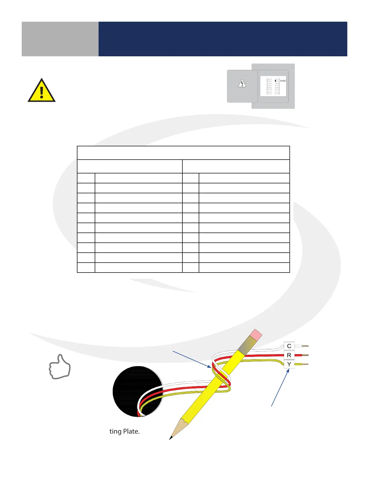
Step 1. Determine the desired wiring conguration for the ST880ZB Thermostat. The following
chart shows the terminal designations for gas, electric or oil (Non-HP) and heat pump (HP)
installations. Appendix A provides reference wiring diagrams for typical thermostat installations.
Step 4. Install the Mounting Plate.
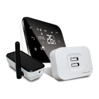
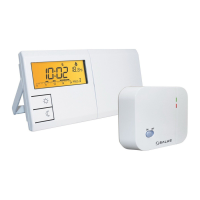
Module 4 – Wireless HVAC Thermostats
ST880ZB Optima Zigbee Thermostat
Section 2
Installation – Mounting & Wiring
Table 2.1: ST880ZB Optima Zigbee Thermostat Wiring Reference
Gas, Electric or Oil (Non-HP) Heat Pump (HP)
RC 24 VAC for Cooling System R 24 VAC for Heat Pump
RH 24 VAC for Heating System -- Jumper to R
C 24 VAC Common Return C 24 VAC Common Return
-- Reserved L System Monitor
Y1 Single / 1st Stage Cooling Y1 Single / 1st Stage Compressor
Y2 2nd Stage Cooling Y2 2nd Stage Compressor
W1 Single / 1st Stage Heating W1 Emergency Heat
W2 2nd Stage Heating O/B Changeover Valve
G Fan Signal G Fan Signal
-- Reserved -- Reserved
Step 2. If replacing an existing thermostat, review and record the existing wiring conguration:
• Remove thermostat from the wall to expose the wiring terminals
• Take a photograph or note the wire colors and designations (see wiring reference above)
• Attach wire labels provided to each of the existing thermostat wires
Step 3. Remove existing thermostat.
BEFORE BEGINNING the installation procedure,
turn o power to the heating system.
LABEL WIRES TO CORRESPOND
TO THERMOSTAT TERMINALS
WRAP WIRES AROUND A PENCIL OR
SIMILAR OBJECT TO PREVENT THEM
FROM FALLING INTO THE WALL VOID
 Loading...