10
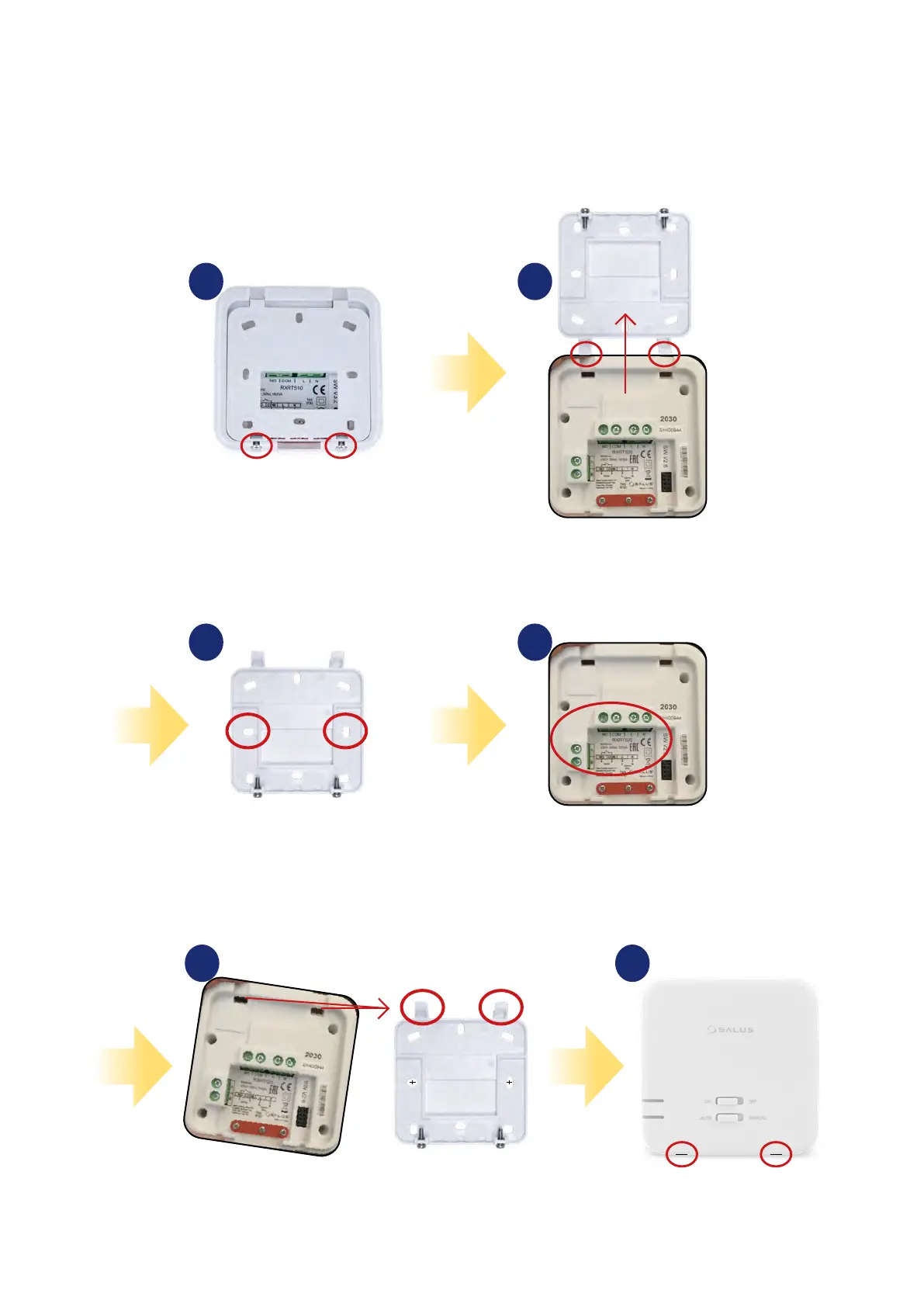
3.3 Wall mounting of the receiver
Wall mounting the receiver: drill two ø6 mm holes in the wall. Insert the plugs and, by putting the plate to the wall (included in the set), put the two
screws through the holes and then screw them in. Connect the necessary cables to the receiver. Next, hang the receiver on the board using the handles
designed in the receiver, marked in the picture below.
Loosen the screws with a scre-
wdriver just enough to tilt the
back housing.
Attach the back housing to the wall
(keeping the correct positioning of the
plastic „hinges”) using the marked holes
(see the picture above).
Put the receiver from above on the back
housing attached to the wall, according to
the position of the plastic „hinges”.
Tighten the screws from the
bottom of the back housing.
Tilt the receiver cover upwards
(according to the position of the
„hinge”).
Then, correctly connect the wires
included in the set with the
receiver (see „connection diagrams”
on page 11).
1
3
5 6
2
4
3
.. ..