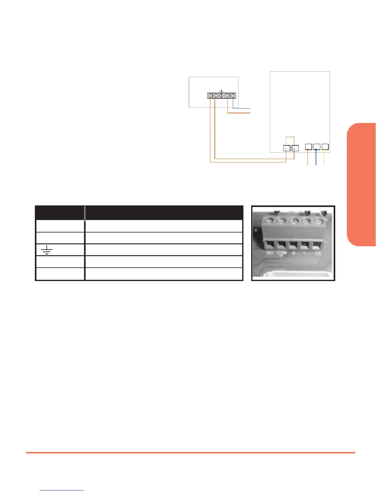
TYPICAL WIRING INSTALLATIONS
The RXST625 receiver is wired the
same way no matter if you are
wirings 240V or 24V, the receiver
will always need a 240V Live and
Neutral feed connected into L & N
terminals. The COM and NO is to
be connected to the boilers
External Loop (see diagram
below), if connected in this way
the receiver relay can only switch
voltage supplied by the boiler.
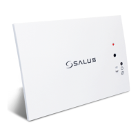
SETTING UP RF COMMUNICATION:
Ensure that the slide switches are in AUTO and ON positions and then press
the sync button. Press and hold the SYNC button for at least 3 seconds,
then release. The receiver will now enter pairing mode, the green LED will
now turn red to indicate that the receiver is ready to pair with the
thermostat*.
While the signal is being received, the red LED will stay on until the pairing
is successful, when pairing is successfull the red LED will turn green.
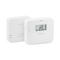
* For full instructions on thermostat pairing see:
RT505TX Manual - Page 13 ST325TX Manual - Page 15
RT305TX Manual - Page 9 ST625TX Manual - Page 11
RXST625 INSTRUCTION MANUAL
9
These electrical connections are shown in the table below:
Terminal Function
COM Common Contact (volt free input)
NO Normally Open Contact (volt free output)
Earth Parking (No electrical connection)
L Incoming Mains - Live
N Incoming Mains - Neutral