Do you have a question about the Salus RXVBC605 and is the answer not in the manual?
Lists essential requirements of EC Directives for product compliance.
Emphasizes fitting by a competent person and adherence to wiring regulations.
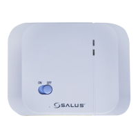
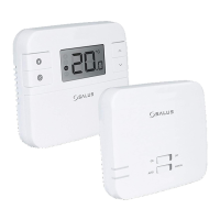
Highlights LED status, ON/OFF switch, and 868 MHz communication.
Details suitable location, power supply, and fuse requirements.
Explains the function of each terminal connection on the receiver.
Illustrates how to connect the receiver to a boiler's external loop.
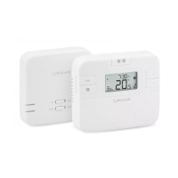
Guides on pairing the thermostat with the RXRT505/RT305TX receiver.
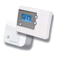
Guides on pairing the thermostat with the ST325TX/ST625TX receiver.
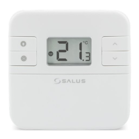
Lists LED status, manual override, and 868 MHz communication.
Details suitable location, power supply, and fuse requirements.
Details terminal functions for the RXST625 receiver.
Steps for synchronizing the RXST625 receiver with a thermostat.
Explains various LED signal combinations and their meanings.
Provides a quick reference for control operations like Auto, Manual, On, Cycle, Off, Sync.
Explains how the receiver operates in automatic mode and handles signal loss.
Details operation when the receiver ignores RF signals and uses manual control.
Describes failsafe modes (On, Cycle, Off) and their LED indications.
Highlights LED status, plug-in connection, 3-position switch, and 868 MHz.
Explains the unit's role as an RF receiving unit for boiler ON/OFF switching.
Warns against touching electrical components and stresses mains isolation.
Provides initial steps for installing the boiler control onto the boiler.
Details steps for connecting the module, checking its operation, and setting the switch.
Guides the user through pairing the RF integral boiler module with a thermostat.
Identifies and explains the LED, Mode Switch, and SYNC Button.
Highlights LED status, plug-in connection, 3-position switch, and 868 MHz communication.
Explains the unit's role as an RF receiving unit for boiler ON/OFF switching.
Discusses RF range and factors affecting transmission distance.
Warns against touching electrical components and stresses mains isolation.
Provides steps for removing the boiler's outer casing and fascia panels.
Details steps for plugging in the connector block and securing the module.
Guides on setting the module switch to OFF, ON, and then AUTO.
Explains how the boiler control operates in AUTO mode, receiving signals from the thermostat.
Explains operation when the switch is set to MANUAL ON, keeping the boiler on.
Explains operation when the switch is set to OFF, disabling thermostat signals.
Identifies and explains the LED, Mode Switch, and SYNC Button.
Guides the user through pairing the RF integral boiler module with a thermostat.
Details operating frequency, range, and environmental operating conditions.
Covers model, type, power, switching, RF specs, and protection rating.
Details operating frequency, range, and environmental operating conditions.
Details operating frequency, range, and environmental operating conditions.
| Mobile App | No |
|---|---|
| Power Supply | 2 x AA Batteries |
| Display | LCD |
| Temperature Range | 5°C to 35°C |
| Hysteresis | 0.5°C |
| Voltage | 230V AC |
| Stages | 1 |
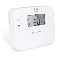
| Programming | 7-Day Programmable |
| Output | Relay |