11
L, N - power supply 230V
- NSB - night temperature reduction
(230V output - in MASTER thermostat)
(230V input - in SLAVE thermostat)
- SL - 230 V AC actuator control signal
NC, NO - voltage-free output
- fuse
Legend:
Symbols explanation:
Thermal actuator
Pump logic module (for KL06) connection diagram
Pump and boiler logic module (for KL06) connection diagram
Pump
Boiler - Boiler connection* - Boiler’s
contacts for ON/OFF thermostat
(according to the boiler’s instructions)
PL07
PODŁĄCZENIE KOTŁA *
L
1
2
3
4
AC 230V lub 24V
N
MAX
5 (2) A
BOILER CONNECTION*
NC
NO
PL06
PODŁĄCZENIE KOTŁA *
NC
NO
PL06
L N
MAX
5 (2) A
AC 230V lub 24V
BOILER CONNECTION*
SLAVEMASTER
L
AC 230V
L
N
N
1 - 6 Strefy
KL06-M
Power
L N
L N
T30NC
max 6
na strefę
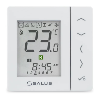
RT10 // RT20
Np. Np.
L N
1 - 6 Strefy
L N
L N
T30NC
max 6
na strefę
RT520
COM NO
lub
NC
NO
PODŁĄCZENIE KOTŁA *
L
AC 230V
L
N
N
1 - 6 Strefy
KL06-M
Power
L N
L N
T30NC
max 6
na strefę
RT10 // RT20
Np. Np.
L N
1 - 6 Strefy
PL06
L N
L N
T30NC
max 6
na strefę
RT520
COM NO
lub
NC
NO
L N
MAX
5 (2) A
AC 230V lub 24V
L
AC 230V
L
N
N
1 - 6 Strefy
KL06-M
Power
L N
L N
T30NC
max 6
na strefę
RT10 // RT20
Np.
Np.
1 - 6 Strefy
PL06
L N
L N
T30NC
max 6
na strefę
RT520
COM NO
lub
NC
NO
PODŁĄCZENIE KOTŁA *
L
AC 230V
L
N
N
1 - 6 Strefy
KL06-M
Power
L N
L N
T30NC
max 6
na strefę
RT10 // RT20
Np. Np.
L N
1 - 6 Strefy
PL06
L N
L N
T30NC
max 6
na strefę
RT520
COM NO
lub
NC
NO
L N
MAX
5 (2) A
AC 230V lub 24V
or
or
BOILER CONNECTION*
1-8 Zones1-8 Zones1-8 Zones
max 6
per zone
max 6
per zone
max 6
per zone
L L LN N N
e.g.
VS30W/VS30B
e.g.
VS35W/VS35B
VS35W/VS35B
 Loading...