b c
d
a
e min.
f Max.
12
A
설치
/ Mounting
03.
/
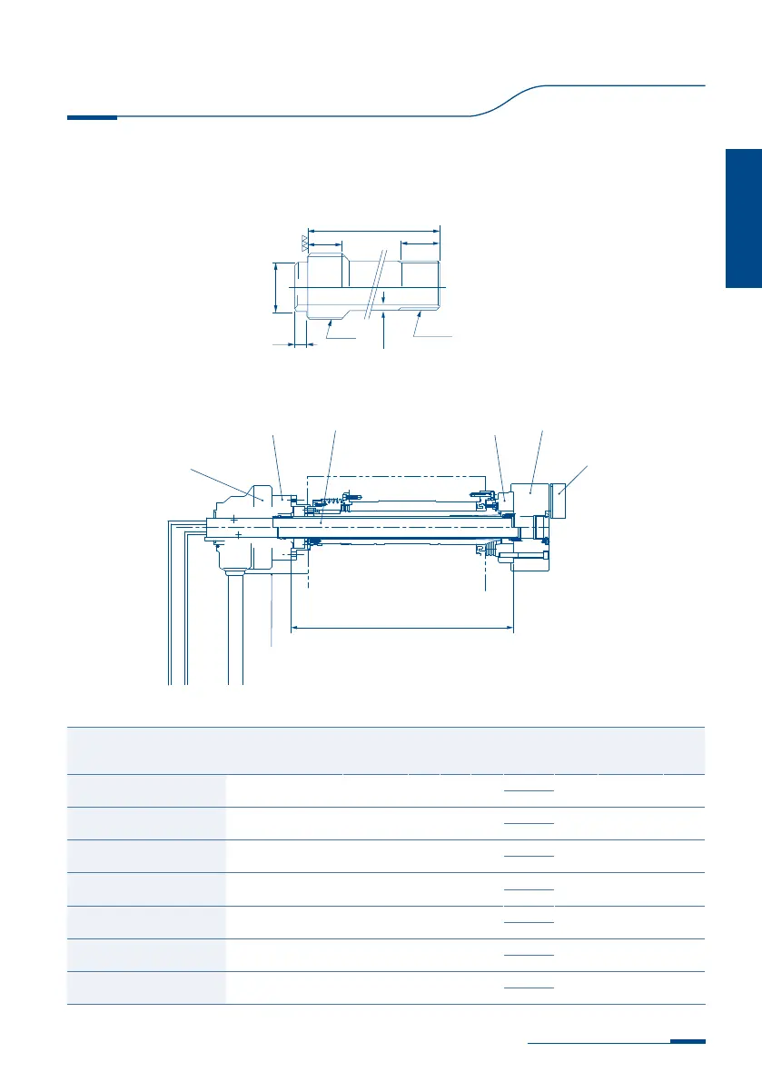
3-1. 드로우 파이프 제작
드로우 파이프의 길이는 아래 규격에 따라 주
십시오.
3-1. Manufacture of drawpipe
The following Figs. 2, 2-1 and table
indicate how to determine the length
of the drawpipe.
13
Instruction Manual
Instruction Manual
드로우 파이프 상세도 / Detailed Drawpipe
Fig.2
Fig.2-1
드로우 파이프 설치도 / Mounting of Drawpipe
나사
Thread
실린더 탑죠
실린더아답터 드로우 파이프 척척아답터
선반
지지대
Cylinder
Top Jaw
Cylinder adaptor Draw pipe
Chuck
Chuck Adaptor
NC Lathe
Support
형식 / Type /型式
실린더
Cylinder
气缸
a b c d(f7) e Min. f Max. L
HCH-04 HYH-0933 M38 x 1.5P 25 20 34
-0.025
3.5 M28X1.5 A+31.5
-0.050
HCH-12 SH-19082 M90 x 2.0P 35 40 84
-0.036
5.0 M88X2.0 A+53.0
-0.071
HCH-15 / HCHT-15 / HCHF-15 SH-25011 M130 x 2.0P 45 40 123
-0.043
6.5 M130X2.0 A+65.0
-0.083
HCH-18 / HCHF-18 SH-25011 M130 x 2.0P 45 40 123
-0.043
6.5 M130X2.0 A+65.0
-0.083
HCH-21 / HCHF-21 SH-25011 M130 x 2.0P 45 40 123
-0.043
7.5 M155X3.0 A+65.0
-0.083
HCH-24 / HCHF-24 SYHL-2816 M130 x 2.0P 45 40 123
-0.043
7.5 M175X3.0 A+76.0
-0.083
HCH-32 / HCHF-32 SYHL-2816 M130 x 2.0P 45 40 123
-0.043
7.5 M175X3.0 A+74.0
-0.083