EB 2520 EN 17
Design and principle of operation
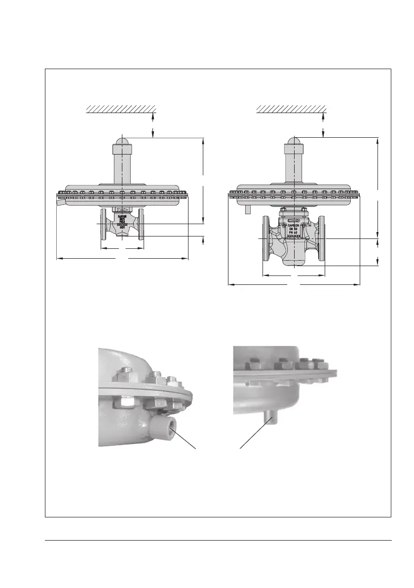
Dimensional drawings
DN15 to 25 DN32 to 50
H
L
min. 150 mm
H
L
min. 150 mm
ControllineconnectionG¼,forA=40,80,
160and320cm²
ControllineconnectionG¼,forA=640and
1200cm²
Thecontrollineconnectionisturnedby90°inthedrawing.Theconnectionisnormallylocated
oppositethesidewiththearrowindicatingthedirectionofow.
G¼tting
Controllineconnectionatthesideoftheactuator
housing
Controllineconnectiononthebottomofthe
actuator housing
Fig.6: Dimensions of Type2405