EB 2520 EN 23
Mounting and start-up
Control line
FittingwithG¼femalethread(9)ontheac-
tuator housing. Route the control line on site
preferablyusinga6mmor¼“(stainless)
steel pipe.
Always connect the control line connection
forpressuretapping(seeFig.7)directlyto
the tank or vessel as the medium is in the ex-
panded state and no turbulence occurs at
this point.
If the pressure is to be tapped at a straight
pipeline section, the largest possible distance
to the regulator must be kept (at least 6 x
DN).Connectthecontrollineatthesideor
on top of the horizontally running main
pipeline. If possible, place the point of pres-
sure tapping in a pipe expansion.
Installanypipettings(e.g.restrictions,
bends, manifolds or branches), that may
causeturbulenceintheow,sufcientlyfar
away from the control line connection (at
least 6 x DN).
Optionally, a ready-mounted control line is
availableforsetpointranges0.8to2.5bar,
2to5barand4.5to10bar.Thisoption
mustbespeciedintheorder(seeFig.10).
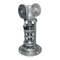
Fig.10: Control line
Regulator damage due to condensed water.
In applications in which the gas can liquefy,
condensate may form in the control line,
causing damage to the regulator. To allow
condensate to run back into the tank, install
the control line with an approximate 10%
slope to the pressure tapping point at the
tank or pipeline (see Fig.7).
Leakage line connection
The regulator in the special version is deliv-
ered with a leakage line connection. In this
version, the opening to the set point adjust-
ment is additionally sealed by a cap.
ConnecttheleakagelinetotheG¼female
threadttingontopoftheactuatorhousing.
In the event of a defective diaphragm (dia-
phragm rupture) in the actuator, any process
medium that escapes is fed through a leak-
age line to a safe location.
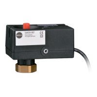
Fig.11: Leakage line connection G¼
NOTICE
!