measured variable have been stored, the
logging is stopped. However, the test is still
completed. The
Measured data storage out
of memor
y alarm is generated. The
Recom
-
mended sampling time,
which should not be
shorter, if at all possible, is calculated from
the
Duration of the test.
The Display section in TROVIS-VIEW 3
shows the
Progress flag
in percent.
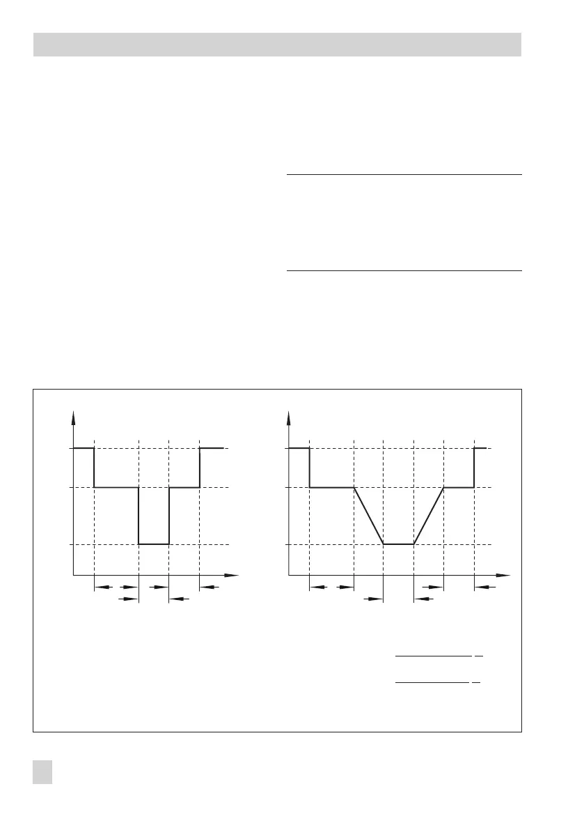
1. Step response function, Fig. 2 left
The step response function is activated when
the
Activation of the ramp function
parame
-
ter is set to "Off".
The valve is moved in steps to the
Step end
position (pos. 3) during the first half of the
test and to the
Step start
position (pos. 2)
during the second half of the test.
2. Ramp function, Fig. 2 right
The ramp function is active when the
Activa
-
tion of the ramp function
parameter is set to
"On".
Note!
A step before the partial stroke test can be
prevented by allocating the value of the
manual reference variable w to the
Step
start
parameter.
The valve is moved to the
Step end
(pos. 3)
and
Step start
(pos. 2) positions with fixed
velocities (v
1
and v
2
) set by the
Ramp time
(falling)
and
Ramp time (rising)
parameters.
10 EB 8388-1 EN
ESD functions
Pos. 1
Pos. 2
Pos. 3
t
1
t
2
t
2
[%]
[s]
Pos. 1
Pos. 2
Pos. 3
t
1
t
2
t
2
[%]
w
w
[s]
t
t
v
1
v
2
Fig. 2 · Courses of the partial stroke tests with step response (left) and ramp function (right)
Valve positions:
Pos. 1 = Required manual
reference variable w
Pos. 2 = Step start
Pos. 3 = Step end
Times:
t
1
= Settling time before test start
t
2
= Delay time after step
Velocities:
v
1
=
100
Ramp time (falling)
%
s
v
2
=
100
Ramp time (rising)
%
s
Step response
Ramp function

 Loading...