EB 6116 EN 29
Mounting and start-up
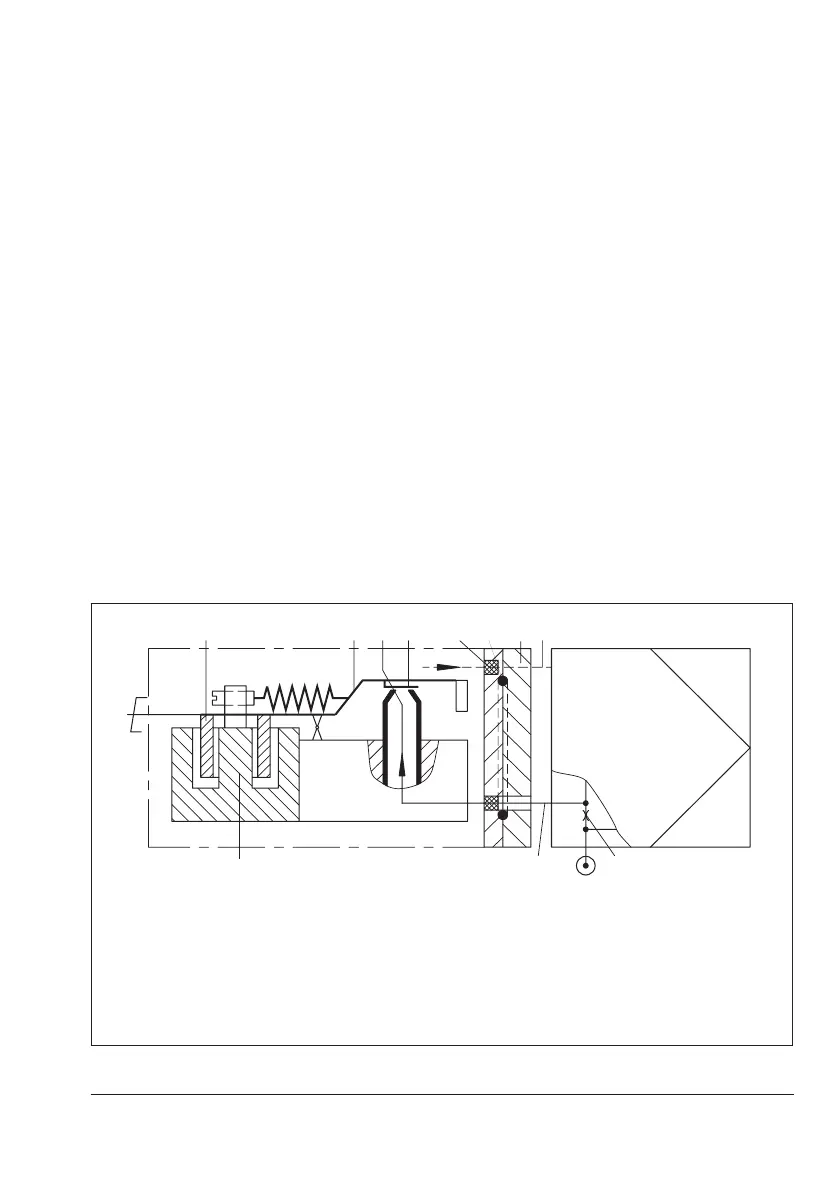
5.5.1 Principle of operation
When operated, the supplied direct current i
owsthroughtheplungercoil(2)locatedin
theeldofapermanentmagnet(3).Atthe
balance beam (1), the force of the plunger
coil, which is in proportion to the current, is
balanced against the force of the dynamic
backpressure. The backpressure is produced
ontheapperplate(6)bytheairjetleaving
the nozzle (7).
The air supply for the nozzle is taken from
the pneumatic positioner (connection to the
pneumaticinputsignal–inputsignal27).
5.5.2 Accessories
Certain mounting accessories are required
for attachment of a positioner (see sec-
tion3.3).
5.5.3 Mounting position of the
converter
Î Mount the converter horizontally using
the adapter (8, 9) onto the control valve
or positioner. In this case, the cable entry
must face sideways away from the con-
trol valve or positioner.
Î Make sure the O-ring (10) to seal the en-
closure is inserted correctly.
2
1
7
6
13
8(9)
11
10
Positioner
Input signal 27
Supply air
Type6116
1 Balancebeam
2 Plunger coil
3 Permanent magnet
6 Flapper plate
7 Nozzle
8 Adapter (3766)
9 Connecting piece
10 O-ring
11 Vent plug
13 Flameprotectionlter
14 Restrictor with air supply
Fig.12: Functional diagram of version mounted on a positioner