5-4 EB 5573 EN
Installation
Overvoltage protection
− If signal lines are installed outside build-
ings or over large distances, make sure
appropriate surge or overvoltage protec-
tion measures are taken. Such measures
are indispensable for bus lines.
− The shield of signal lines installed outside
buildings must have current conducting
capacity and must be grounded on both
sides.
− Surge diverters must be installed at the
control cabinet inlet.
Connecting the heating controller
Î If the controller housing and the base
have not yet been separated: unscrew
the screws on the bottom left and top
right of the housing to open it to connect
the wiring.
Î To feed through cables, make holes in the
marked locations at the top, bottom or
backofthebaseofthehousingandt
suitable grommets or cable glands.
Î For wall mounting: ensure that the lines
are not subject to torsion or bending by
taking suitable precautions, e.g. a cable
duct, before inserting them into the base.
Î ConnectasshowninFig.5-2or
Fig.5-3.
Connecting sensors
The wire cross-section of the sensor cables
mustnotbesmallerthan0.5mm².
Wiring of a room panel
Î ConnectasshowninFig.5-4.
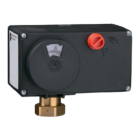
Connecting actuators
− 0to10Vcontroloutput:usecableswith
a minimum wire cross-section of
0.5mm².
− Three-steporon/offoutputs:connectca-
bles with a minimum wire cross-section
of1.5mm²suitablefordamplocations
to the terminals of the controller output.
We recommend checking the operating
direction on start-up.
Connecting pumps
Connectallcableswithaminimum1.5mm²
wire cross-section to the terminals of the
heating controller as illustrated in the wiring
diagram.
The electric actuators and pumps are not au-
tomatically supplied with a voltage by the
heating controller. They can be connected
over terminals 20, 22, 25 and 28 to an ex-
ternal voltage supply. For an internal power
supply, place a jumper from terminal 18 to
terminals 20, 22, 25 and 28.
Note