12
Installation Procedure
English
Installation Procedure
Silence mode controller wiring diagram with
External controller
2Pin (RED)
4Pin(RED)
Non-voltage
contact
External controller
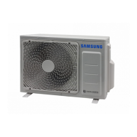
Connecting the main power cable and outdoor-
to-AHU Control Unit communication cable
AHU Control Unit
F1
F2
Outdoor Unit
Main power cable
Communication cable
Cable tie
Cable tie
NL
F1 F2
NOTE
• Lay the electrical wiring so that the front cover does
not rise up when doing wiring work and attach the
front cover securely.
• Ground wire for the outdoor unit connection cable must
be clamped to a soft copper tin-plated eyelet terminal.
• The appearance of the unit may be different from the
picture depending on the model.
Outdoor-to-AHU Control Unit communication cable
• Connect the cables to the terminal board using the
compressed ring terminal.
• Cover a solderless ring terminal and a connector part
of the power cable and then connect it.
• Connect the rated cables only.
• Connect using a driver which is able to apply the rated
torque to the screws.
• If the terminal is loose, fire may occur caused by arc. If
the terminal is connected too firmly, the terminal may
be damaged.
Tightening torque
ɵ˙ଗ˙ϩ Ęଗ
M4 0.87 to 1.30 0.8 to 1.2
M5 1.45 to 2.17 2.0 to 3.0
CAUTION
• When connecting cables, you can connect the cables to
the electrical part or connect them through the holes
below depending on the spot.
• Connect the communication cable between the indoor
and outdoor units through a conduit to protect against
external forces, and feed the conduit through the wall
together with refrigerant piping.
• Remove all burrs at the edge of the knock-out hole and
secure the cable to the outdoor knock-out using lining and
bushing with an electrical insulation such as rubber and so on.
• Must keep the cable in a protection tube.
• Keep distances of 1.97 inch(50mm) or more between
power cable and communication cable.
• When the cables are connected through the hole,
remove the Plate bottom.
Power supply
Power supply Max/Min (V) Power cable
ߢעࡡߣߡߩࣗߣߤߡǤࡡߧߡ²і ±10%
ߡࢋߡߡߤߪʀ˵ࠟ
࣍ߣࢋߦࠟ࣎ࡡߤиθʪϑ
Communication cable
18 AWG, 2 wires
ki]_TXYW][hTWWptjhjG|GvhhluUGGGXY YWYYTXWTZXGGG㝘㤸GXWa[_a\^
 Loading...