ENGLISH-44
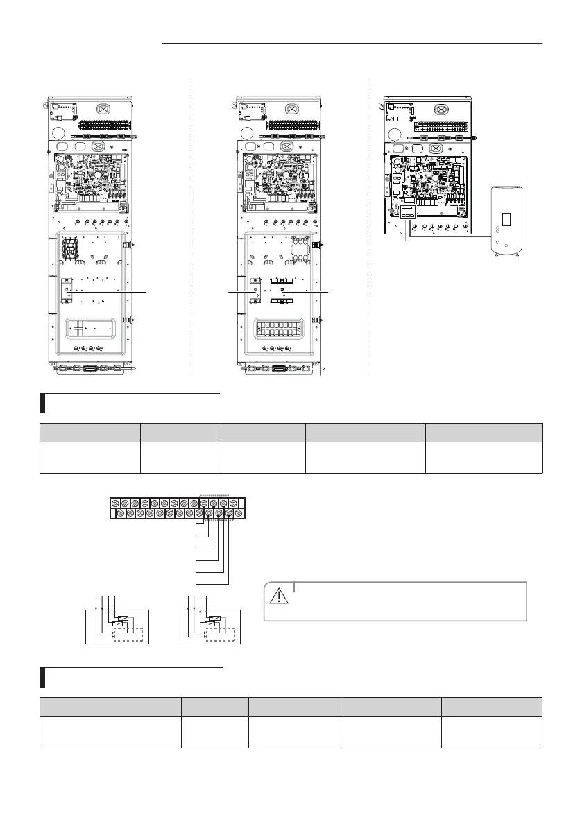
Wiring work
1 phase 3 phase Booster heater (DHW, assembly in factory)
1 Phase
ELCB
1 Phase
ELCB
3 Phase
ELCB
DHW Tank
Connection of the thermostat
Description No. of wires Max. current Thickness Supply Scope
Room Thermostat 4 22mA
> 0.75 mm
2
, H05RN-F or
H07RH-F
Field supply (220-240V~,
Input)
N L
C1
H1
N L
C2
H2
B24 : THERMOSTAT02_HEATING (H2)
THERMOSTAT01 THERMOSTAT02
B23 : THERMOSTAT02_COOLING (C2)
B22 : THERMOSTAT01_HEATING (H1)
B21 : THERMOSTAT01_COOLING (C1)
B20 : Live (L)
B19: Neutral (N)
1. Before the installation, hydro unit should be turned o.
2. Using the appropriate equipment to correct position of terminal
block as shown on the diagram.
3. Make sure what type is you use.
- Contact signal must be “ L “. When you install two thermostats,
thermostat2 is prior to thermostat1.
• Product will not operate when signal for cooling and
heating mode is inputted at the same time.
CAUTION
Connection of the 2-way valve
Description No. of wires Min. / Max. current Thickness Supply Scope
Motorized 2-way valve to shut o
UFH loops during cooling.
2+ground 10mA / 50mA
> 0.75 mm
2
, H05RN-F
or H07RH-F
Field supply (220-
240V~, Output)
 Loading...