1. Precautions 1-1 ~ 1-6
1-1 Safety Precautions (1-1)
1-2 Servicing Precautions (1-3)
1-3 ESD Precautions (1-4)
1-4 Handling the optical pick-up (1-5)
~ 2-6
3. Disassembly and Reassembly 3-1 ~ 3-8
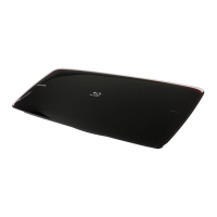
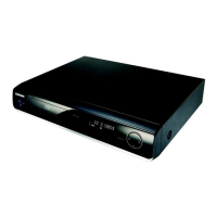
3-1 Cabinet and PCB (3-1)
3-2 PCB Location (3-7)
4. Trouble Shooting 4-1 ~ 4-22
4-1 Trouble Shooting (4-2)
4-2 Software Update (4-21)
5. Exploded View and Parts List 5-1 ~ 5-18
5-1 Cabinet Assembly (5-2)
5-2 Electrical Parts List (5-4)
6. PCB Diagrams 6-1 ~ 6-10
6-1 Wiring Diagram (6-2)
6-2 Main PCB (6-3)
6-3 S.M.P.S PCB (6-6)
6-4 Front PCB (6-8)
6-5 Power Key PCB (6-9)
7. Schematic Diagrams 7-1 ~ 7-22
7-1 All block Diagram (7-2)
7-2 Power (7-3)
7-3 S.M.P.S (S.M.P.S PCB) (7-5)
7-4 SMP8634 DDR SDRAM (Main PCB) (7-6)
7-5 SMP8634 Flash Memory (Main PCB) (7-7)
7-6 Nand Flash, Controller (Main PCB) (7-8)
7-7 SMP8634 Power, Decoupling (Main PCB) (7-9)
7-8 Sil9134 HDMI (Main PCB) (7-10)
7-9 HDMI-CEC (Main PCB) (7-11)
7-10 Ethernet contol (Main PCB) (7-12)
7-11 Audio (Main PCB) (7-13)
7-12 SMP8634 GPIO Control, JTAG, Debug (Main PCB) (7-14)
7-13 MM1757 Analog Video Out (Main PCB) (7-15)
7-14 PATA Control (Main PCB) (7-16)
7-15 Power (Main PCB) (7-17)
7-16 PCI, ETC (Main PCB) (7-18)
7-17 Front Interface (Main PCB) (7-19)
7-18 Front (Front PCB) (7-20)
7-19 Power Key (Power Key PCB) (7-21)
CONTENTS CONTENTS