Schematic Diagrams
Samsung Electronics This Document can not be used without Samsung’s authorization 7-3
7-2 Power
7-2-1 About S.M.P.S (Ringing Choke Converter Method)
u Terms
1) 1st : Common power input to 1st winding.
2) 2nd : Circuit followings output winding of transformer.
3) f (Frequency) : Switching frequency (T : Switching cycle)
4) Duty : (Ton/T) x 100
7-2-2 Circuit description [FLY-Back RCC(Ringing Choke Converter)] Control
(a) AC Power Rectication/Smoothing Terminal
1) A01~04 : Convert AC power to DC (Wave rectication).
2) CIS01 : Smooth the voltage converted to DC.
3) LIS01, LISO2, CIS04, CIS05 : Noise removal at power input/output.
4) RIS04 : Rush current limit resistance at the momemt of power cord insertion.
· Without PLRU1, the bridge diode might be damaged as the rush current increases.
Fig. 7-1
Fig. 7-2
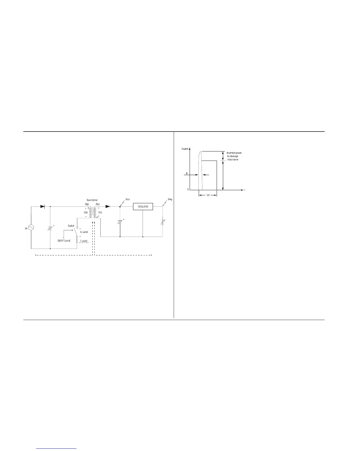
(b) SNUBBER Circuit :
RIS02, RIS03, CIS08, CIS07, DIS05
1) Prevent residual high voltage at the terminals of
switch during switch off/Suppress noise.
High inverted power occurs at switch off,
because of the 1st winding of transformer :
(V=-L1 xdi/dt. L1 : Leakage Induction)
A very high residual voltage exist on both terminals
of ICIS01 because dt is a very short.
2) SNUBBER circuit protects ICIS01 from damage
through leakage voltage suppression by RC,
(Charges the leakage voltage to DIS05 and CIS08
and discharges to RIS03, RIS02).
3) CIS07 : For noise removal
(c) IC1S01 Vcc circuit
1) ICIS01, RIS05, RIS07,RIS08 : ICIS01 driving resistance (ICIS01 works through driving resistance at power
cord in)
2) ICIS01 Vcc : RIS05, RIS07, RIS08
q Use the output of transformer as Vcc,because the current starts to ow into transformer while ICIS01 is
active
w Rectify to DIS07 and smooth to CIS09.
e Use the output of transformer as ICIS01 Vcc : The loads are different before and after ICIS01 driving.
(Vcc of ICIS01 decreases below OFF voltage , using only the resistance dut to lode increase after ICIS01
driving.)
 Loading...