A
April WhiteAug 19, 2025
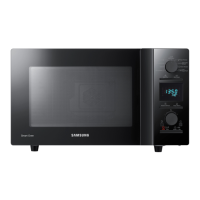
Why is my Samsung Microwave Oven not heating food properly?
- LLisa MasseyAug 20, 2025
If your Samsung Microwave Oven is taking longer to cook food, it could be due to a decrease in power source voltage, an open or loose wiring of the magnetron filament circuit (causing intermittent oscillation), or the aging of the magnetron. It is recommended to consult an electrician.