2. Installation
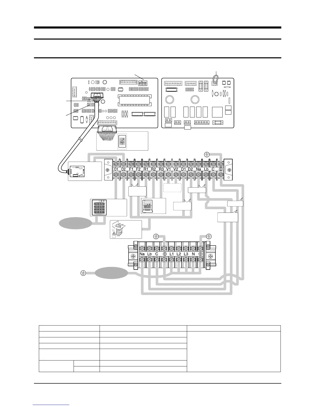
2-1 Wiring diagram
Samsung Electronics
2-1
Receiver &
Display Unit
(Optional)
CN20 Connector
Rotary
Digital
Switch
Jumper
Wire
Transmitter
(Optional)
Float Switch
Drain Pump
(Optional)
Wired
Remote
Controller
(Optional)
DIP Switch
MAIN PCB SUB PCB
220-240V~,
50Hz
Float Switch
Power
Communication
Earth
Ventilator
Motor
The following electrical characteristics must be respected.
MODEL
Power
Sub switch
Fuse
Min. size of electric Wires
from/to the indoor/outdoor unit
Size of electric
input wires
20m or less
50m or less
ADH4400G / DH44ZA1(A2)
3Ø, 380-415V~, 50Hz
30A
30A
◆ The power cables are not
supplied with the air conditioner.
The user should purchase them separately.
◆ When connecting the cables to the
main power, you should connect each
cable(L1, L2 & L3) properly.
H07RN-F, 4G, 1.25mm
2
H07RN-F, 3G, 2.5mm
2
H07RN-F, 3G, 4.0mm
2
Note
MAIN POWER
3ø, 380-415V~,
50Hz
MAIN POWER
Drain Pump
Indoor Unit
Outdoor Unit
Centralized
Controller
(Optional)
Cable Specifications
2-00216A(1)-PR 5/19/01 10:04 AM Page 2-1