Do you have a question about the Samsung MAX-670 and is the answer not in the manual?
Safety precautions to prevent damage and protect against hazards like electrical shock and X-rays.
Precautions to follow during servicing to prevent damage and ensure safety.
Handling precautions for ESD-sensitive components to prevent damage from static electricity.
Special safety measures and warning labels related to laser products used in the device.
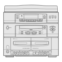
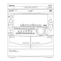
Steps for disassembling the Amp and Tuner section of the device.
Steps for removing the cabinet rear panel and main PCB.
Steps for removing the front cabinet panel.
Steps for disassembling the Cassette Deck and CD section.
Alignment and adjustment procedures for the Tuner section (FM/AM).
Procedures for aligning and adjusting the Cassette Deck section.
Alignment and adjustment procedures for the CD section.
Special circuit descriptions related to the CD section.
Troubleshooting procedures for issues related to the amplifier section.
Troubleshooting procedures for issues related to the cassette deck section.
Troubleshooting procedures for issues related to the CD player section.
Exploded views and parts list for the Amp and Tuner section.
Exploded views of the Cassette Deck and CD section.
Parts list for the Cassette Deck section.
Block diagram of the Amp and Tuner sections.
Block diagram of the Cassette Deck section.
Block diagram of the CD section.
Internal diagrams of Integrated Circuits (ICs) and Transistors (TRs).
Block diagrams for the microcomputer (μ-com) section.
PCB layout diagram for the Amp and Tuner section.
PCB layout diagram for the Front section.
PCB layout diagrams for the Cassette Deck and CD sections.
PCB layout diagram for the Front section.
PCB layout diagram for the 6+1 Key section.
PCB layout diagram for the Tape Key section.
PCB layout diagrams for the CD section.
Wiring diagram for the Amp and Tuner section.
Wiring diagrams for the Cassette Deck and CD sections.
Schematic diagram for the Amp and Tuner section.
Schematic diagram for the Front section.
Schematic diagram for the Cassette Deck section.
Schematic diagram for the CD section.
| Type | Mini Hi-Fi System |
|---|---|
| Number of Discs | 1 |
| CD Player | Yes |
| USB Port | Yes |
| FM Tuner | Yes |
| Bluetooth | No |
| Playable Media | CD, CD-R, CD-RW |
| Tuner | FM |