VTVM
400mV 5%
105KHz 5%
VTVM
(7V 5%)
Max output
and same
phase both
channels.
300mV 0.5dB
Max output
and same
phase (both
channels).
300mV 0.5dB
4-3Samsung Electronics
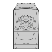
Figure 4-6
Figure 4-7
Cassette Deck
LINE OUT
TP1
V H
Oscilloscope
Recording/Play head
REVERSE
PLAY
Input Output
Azimuth Control Knob
Alignment and Adjustments
1) Before the actual adjustment, clean the
replay/recording head.
2) Measuring tape :
i) MTT-114NA (or equivalent 12.5 kHz AZIMUTH
control).
ii) MTT-150 (or equivalent : Dolby level 200mwb/m)
3) Dolby NR SW OFF
4) The cassette deck is connections as shown in figure4-6.
NOTES
4-2-2 To Adjust Replay Head
Step
Step
To Adjust
To Adjust
Item
Item
Standard
Standard
Remark
Remark
Pre-Setup
Condition
Pre-Setup
Condition
Pre-Setup
Pre-Setup
AZIMUTH
PlayBack
out Level
TP1 OUT
(VTVM is
connected
to the
scope)
Same as
above
After putting MTT
-114NA into Deck 1.
1) Press FWD
PLAY button.
2) Press REV
PLAY button.
PLAY MTT-150
on Deck1.
1) Turn the control
knob to as shown
in Figure 4-6.
2) Adjust the right
control screw to
playback Rev.
Mode.
L-CH : Turn JSR1R
to the right and
left
R-CH : Fixed
After
adjustment
secure it
with
REGION
LOCK.
See the
diagram
for
adjustment
locations
After
adjustment
secure it
with
REGION
LOCK.
See the
diagram
for
adjustment
locations
1
2
AZIMUTH
PlayBack
out Level
TP3 OUT
(VTVM is
connected
to the scope)
Same as
above
After putting
MTT-114NA into
Deck 2.
1) Press FWD
PLAY button.
2) Press REV
PLAY button.
PLAY MTT-150
on Deck2.
1) Turn the control knob
to left and right as shown
in the Figure 4-6.
2) Adjust the right
control screw to
playback Rev. Mode.
L-CH :Turn JSR2R to
the right and left;
R-CH : Fixed
1
2
1) Adjust 1-Deck Replay Level
2) Adjust 2-Deck Replay Level
1) Connect the measuring instruments as shown in Figure 4-8
2) Set the DOLBY NR Switch off.
3) Measuring tape :
MTT-5512 ( or equivalent : normal recording )
4) The input signals supply 400Hz 400mV into AUX IN of AMP (AUDIO OSC).
NOTES
Step
Item
Pre-Setup
Condition
Normal
electric
current for
recording
BIAS OSC.
FREQUENCY
BIAS electric
current
Connect to TP2
as in Figure 4-8
and read
VTVM
Connect the
frequency
counter to
TP1
Connect to
TP1 as in
Figure 4-8
and read the
VTVM
Insert MTT-5512
into Deck 2,
then press
REC button.
Insert MTT-5512
into Deck 2,
then press
REC button.
Insert MTT-5512
into Deck 2,
then press
REC button.
L-CH : DSR2L to
the right and left.
R-CH : Fixed
Turn BIAS oscilla-
tor frequency coil
(LL2) to the right
and left.
L-CH : DSR1L and
R-CH: DSR1R to
the right and left.
See diagram
for adjustment
locations.
See diagram
for adjustment
locations.
See diagram
for adjustment
locations.
1
2
3
4-2-3 To Adjust PlayBack
Figure 4-8
In Out
VTVM
AUDIO OSC
Oscilloscope
Cassette Deck
AUX IN
TP1
Pre-Setup
To Adjust
Standard
Remark