147
B
UILDING
M
ANAGEMENT
S
YSTEM
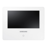
LED indicator
Front
①②③④ ⑤⑥ ⑦⑧⑨
3) Description of parts
Lon
ACK SVC
DMS-Lnet
③
②
①
No
Name
Function
①
LCD display Displays current time or menu.
②
Menu button Access the setting menu.
S/T button
Select function or setting item in the setting menu.
Set button Enter or check setting item in the setting menu.
③
Bottom cover
Unscrew 2 screws on the bottom to remove the
cover and check the cable connections.
No.
Item Name Status
①
Power
1PXFSJOEJDBUPS Turns blue when the power is supplied.
②
CPU Alive
$16PQFSBUJPOJOEJDBUPS
Blinks in orange with 1 second intervals during
normal operation.
③
Ethernet-Linked
Internet connection indicator Turns green during normal connection.
④
Ethernet-Active
Internet data transmission/reception indicator
Blinks in orange during normal transmission/reception.
⑤
COM1~4-TX
Channel 1~4 OnOff controller/Interface
module Data transmission indicator
Blinks in green during normal transmission.
⑥
COM1~4-RX
Channel 1~4 OnOff controller/interface
module Data reception indicator
Blinks in green during normal reception.
⑦
Lon ACK
LonWorks data reception indicator Blinks in green during normal reception.
⑧
Lon SVC
LonWorks device status indicator
Blinks in green during un-configured.
⑨
Check
Indoor/Outdoor unit communication status
indicator
Turns green when there is an error on more than
one indoor/outdoor unit or in communication.
Compatible product
7 Conventional communication outdoor unit requires compatible interface module (MIM-N01) to establish connection
7 MIM-B13D, MIM-B13E, MIM-B04A Interface modules cannot be connected.
7 To connect ERV, MIM-N10 interface module is required.
7 PIM connection is different depending on software version.
- Before 2.6.0.3 : MIM-B16 only
- 2.6.0.3 : MIM-B16N only
- After 2.6.1.
7
: MIM-B16, MIM-B16N
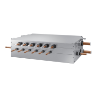
Outdoor unit AM7777X777777
Controller
0O0GGDPOUSPMMFS.$."%/
5PVDIDFOUSBMJ[FEDPOUSPMMFS.$."/
1*.JOUFSGBDFNPEVMF.*.#.*.#/
[¥]UwGG¥UGGGX[^ YWX[TW[TY\GGG㝘䟸G[aZ]aZ\
 Loading...