45
C
ENTRALIZED
C
ONTROL
S
YSTEMS
No.
Name
Description
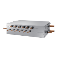
①
F1/F2 communication
connector
Communication connector that connects to outdoor unit /
''
②
Power connector DC 12V
③
Communication LED
Communication indicator LED
(Left LED 3 : No function
Middle LED 1 : Blinks during it communicates with upper
level controller
Right LED 2 : Blinks during it communicates with
outdoor unit and indoor unit)
④
Address setting switch Sets the address of interface module
⑤
Software update
connector
6TJOHUIJTDPOOFDUPS*OUFSGBDFNPEVMFTPGUXBSFDBOCF
updated
⑥
7-segment
Displays the communication status between interface
module and outdoor unit/ERV
⑦
Upper level controller
communication channel
Communication connection channel to upper level
controller R1/R2
⑧
DIP switch
SW1 Description
1
On : Manual address setting /
Off : Auto address setting
2 No function
3 No function
4 No function
Outdoor unit AM7777X777777
Upper level controller
① OnOff controller : MCM-A202D
② DMS2 : MIM-D00A
③ BACnet Gateway : MIM-B17
④ Lonworks Gateway : MM-B18
⑤ S-NET mini : MST-S3W
Compatible Models
Outdoor unit %7.1MVT$"$
Upper level controller
① OnOff Controller: MCM-A202DN
② DMS2 : MIM-D00AN
③ BACnet gateway : MIM-B17N
④ Lonworks gateway : MIM-B18N
⑤ Touch centralized controller : MCM-A300N
(2) Conventional communication outdoor unit ¥ New communication upper level controller
(1) New communication outdoor unit ¥ Conventional communication upper level controller
> Function controller and S-NET 2 Plus are not supported.
t/FXDPNNVOJDBUJPO0VUEPPSVOJU.*./.$."%'VODUJPODPOUSPMMFS9
t/FXDPNNVOJDBUJPO0VUEPPSVOJU.*./.$."%4/&51MVT9
①
④
③
⑤
⑥
②
⑦
⑧
3) Description of parts
;
Note
X
8IFODPOOFDUJOHUPUIFDPOWFOUJPOBMDPNNVOJDBUJPODPOUSPMMFSBEESFTTNVTUCFTFUNBOVBMMZ
regardless to the SW1 setting.
8IFOTFUUJOHUIFBEESFTTNBOVBMMZNBLFTVSFUPTFUUIFBEESFTT
that is not assigned to other deivce already.
X
8IFODPOOFDUJOHUPUIFOFXDPNNVOJDBUJPODPOUSPMMFS48NVTUCF0/UPTFU
UIFBEESFTTNBOVBMMZBOENBLFTVSFUPTFUUIFBEESFTTUIBUJTOPUBTTJHOFEUPPUIFS
compatible interface module or outdoor units.
 Loading...