Samsung Electronics 5-1
5. Alignment and Adjustment
5-1 Mechanical Adjustment
1. Refer to mechanical manual ÒDE-6 (AD68-30200A)Ó for the adjustment and checks of mechanism section.
2. Short between pin 67 of IC601 and GND in order to set the TEST mode (Track Shift Mode).
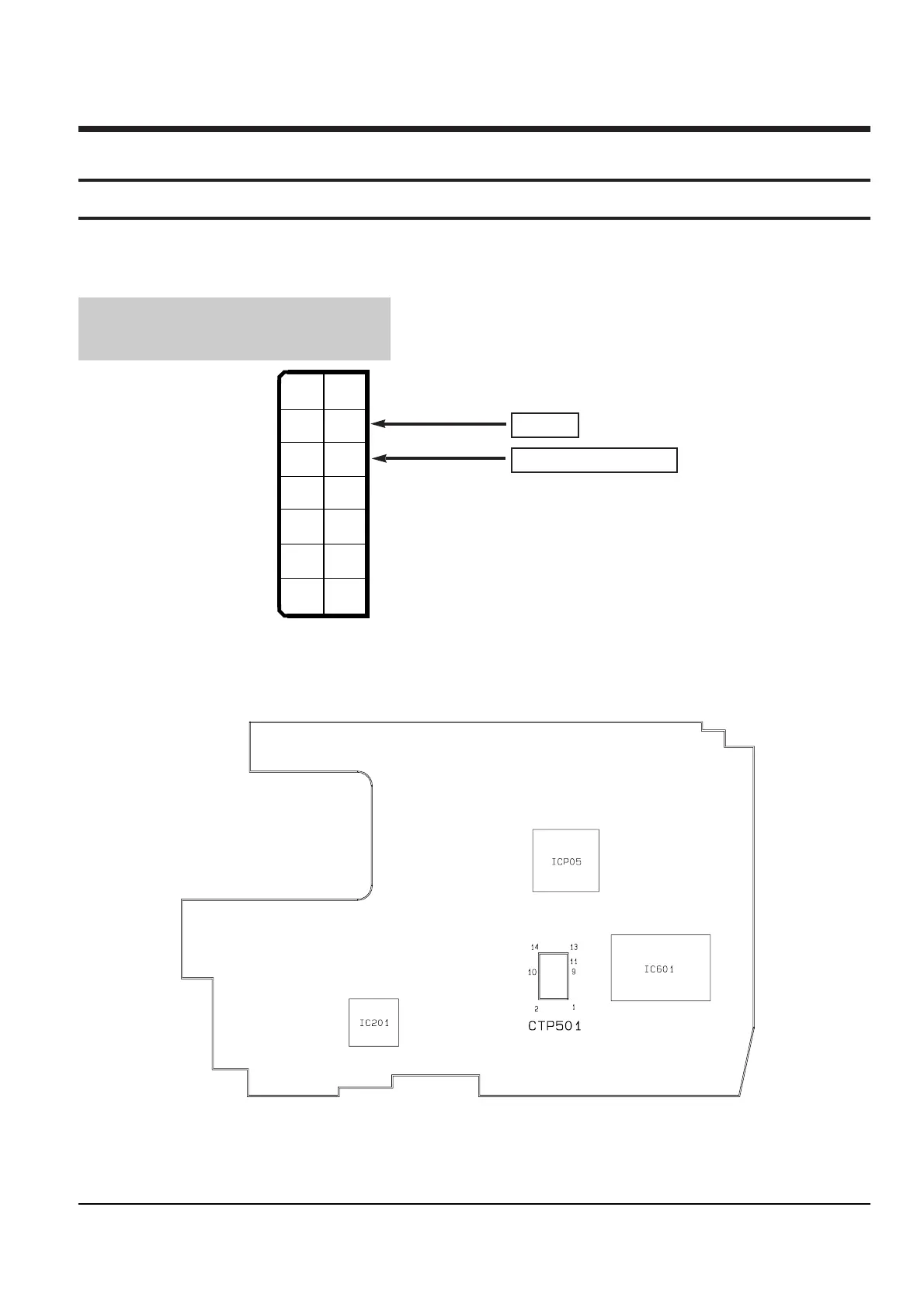
3. The location of test point (See Fig.1)
Test Point :
PB RF - Pin 11 of CTP501
Head Switching Trigger - Pin 9 of CTP501
Fig. 1 Test point
Fig. 2 The location of test point
Main PCB (Component side)
PB RF
Head Switching -Trigger
4. After completing the adjustment, open the pin 67 of IC601 and GND to release the TEST mode.
 Loading...