Samsung Electronics 5-27
Alignment and Adjustment
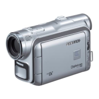
3. R-Sub Brightness
1) Color bar
2) R-OUT
3) Connect an oscilloscope probe to R-OUT.
4) Press the “DATE/TIME(MODE UP)/TITLE
(MODE DOWN)” button so that the OSD state
is “4 R SUB EPR:XX EVR:XX”
5) Adjust the “C/RESET(DATA UP)/Z/RTN
(DATA DOWN)” button so that R-OUT(Red)
level is 8.0Vp-p (pedestal to pedestal).
6) Be sure to press the “MENU/ENTER(CON-
FIRM)” button to memorize setting.
7) The OSD shows “O.K”
5-2-4 (b) ADJUSTMENT
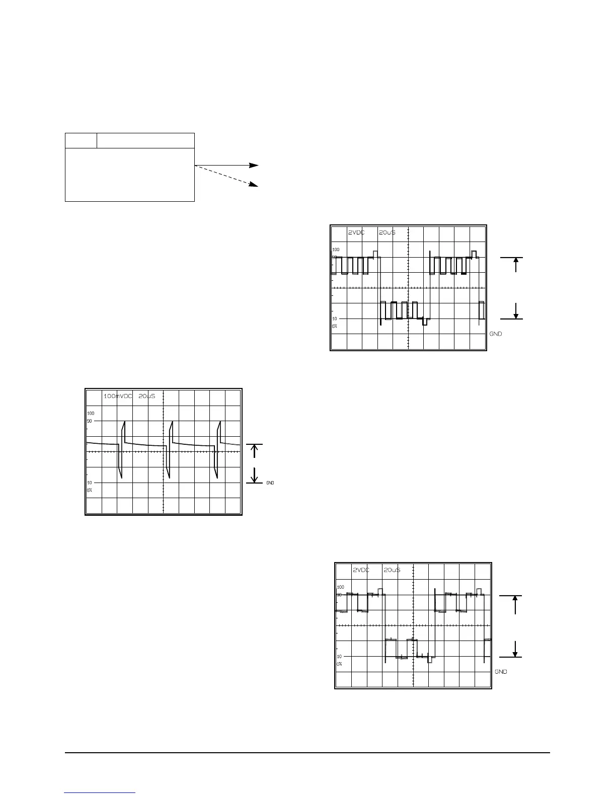
1. PLL
1) Color bar
2) Connect an oscilloscope probe to PLL
3) Press the “DATE/TIME(MODE UP)/TITLE
(MODE DOWN)” button so that the OSD state
is “8 PLL EPR:XX EVR:XX”
4) Adjust the “C/RESET(DATA UP)/Z/RTN
(DATA DOWN)” button so that RPD level is
DC1.8+-0.1Vp-p.
5) Be sure to press the “MENU/ENTER(CON-
FIRM)” button to memorize setting.
6) The OSD shows “OK”
2. Brightness
1) Color bar.
2) G-OUT.
3) Connect an oscilloscope probe to G-OUT.
4) Press the “DATE/TIME(MODE UP)/TITLE
(MODE DOWN)” button so that the OSD state
is “2 BRIGHT EPR:XX EVR:XX”
5) Adjust the “C/RESET(DATA UP)/Z/RTN
(DATA DOWN)” button so that bright(Green)
level is 8.0Vp-p (pedestal to pedestal).
6) Be sure to press the “MENU/ENTER(CON-
FIRM)” button to memorize setting.
7) The OSD shows “O.K”
Test point
Step Adjustment Item
1. Mode and input signal
2. Test point
3. Result and Remarks
ADJ. point
Note :
1. From this point forward, the structure of every adjustment is as follows.
2. See page 5-26 for the location of test points and adjustments.
 Loading...