Samsung Electronics5-36
Alignment and Adjustment
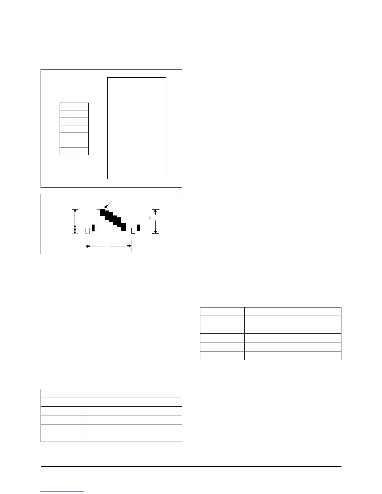
g. Press the “C/RESET(DATA UP)/Z/RTN(DATA
DOWN)” button so that the CN605 PIN13 is
1.0±0.02Vp-p from SYNC to peak level.
h. Be sure to press the “MENU/ENTER(CON-
FIRM)” button of CAMCORDER to memorize
setting.
i. Reset the power source so as to fix the new data
to the camcorder’s EEPROM.
2-6. Y-FM Carrier (NOR)
: This adjustment is performed to set the sync-
tip level of the composite video signal.
Maladjusted Y-FM carrier impact to the play-
back picture, there may be black or white dot
noise.
a. Preparations
b. Connect a power source.
c. Get into the VCR adjustment mode.
d. Press the “DATE/TIME(MODE UP)/TITLE
(MODE DOWN)” button of CAMCORDER so
as to select the address 04.
e. Insert a Normal Tape to the camcorder.
f. Press the START/STOP button on the Rear
board so as to set the camcorder to RECORD-
ING mode.
g. Connect the frequency counter to the addressed
Test Point.
h. Press the “C/RESET(DATA UP)/Z/RTN(DATA
DOWN)” button so as to set the frequency to
4.38MHz ± 0.02MHz
i. Be sure to press the “MENU/ENTER(CON-
FIRM)” button of CAMCORDER to memorize
setting.
j. Reset the power source so as to fix the new data
to the camcorder’s EEPROM.
2-7. Y-FM DEVIATION (NOR)
: This adjustment sets the Y-FM modulation
level in recording. For adjustment, playback
the self-recorded signal and observe the
VIDEO OUT signal.
* Note : It is a little difficult to adjust because you
can check the waveform in playback
mode even though the adjustment is per-
formed in VCR record mode.
So you have to do it carefully.
a. Preparations
 Loading...