12_ introduction
introduction
English English _ 13
INTRODUCTION
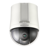
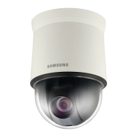
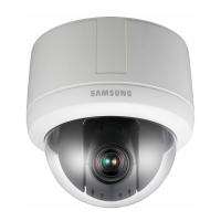
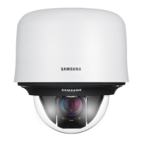
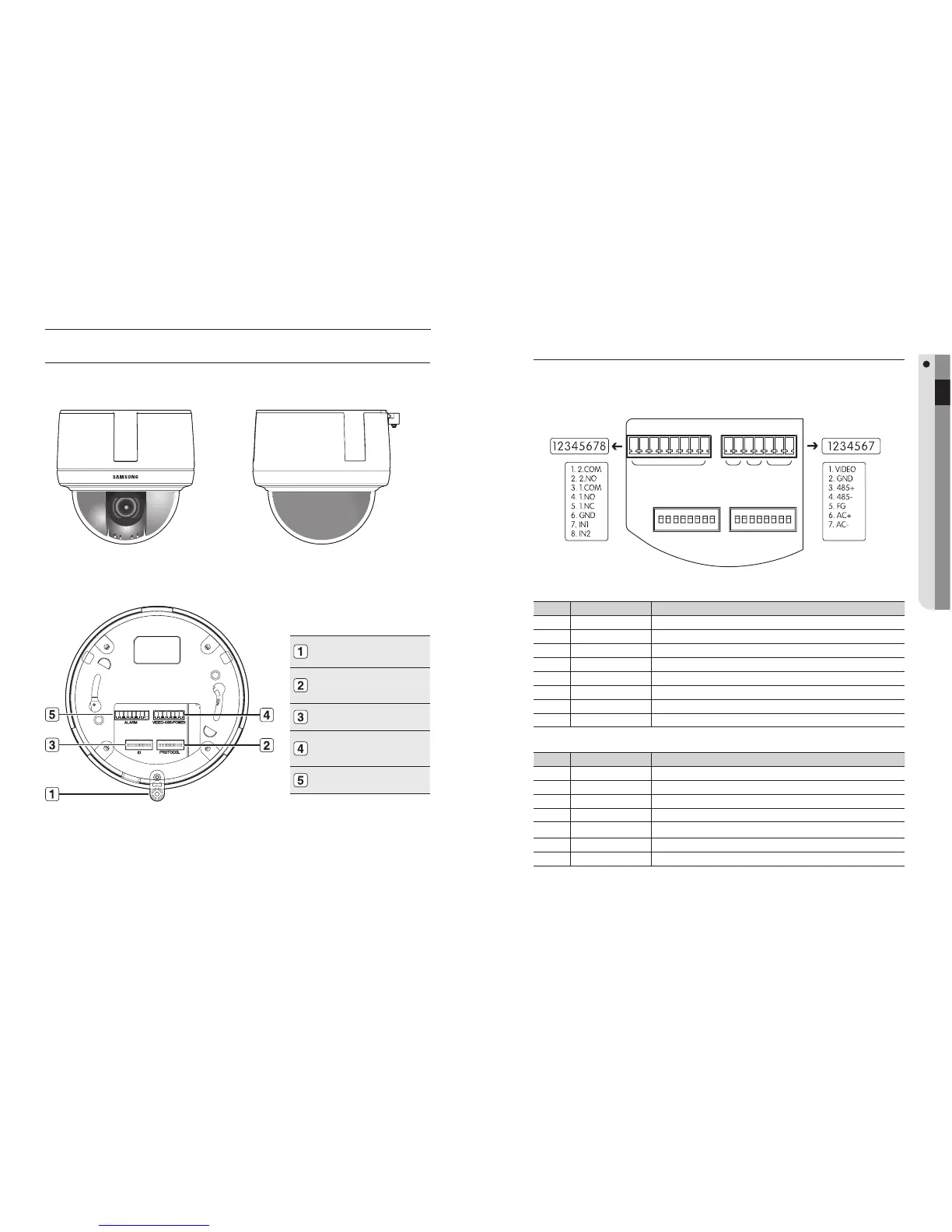
COMPONENT NAMES AND FUNCTIONS
Front❖ Side❖
Bottom❖
For the DIP switch settings, please refer to the “Installing Your Camera” on Page 17.
M
Screw Hole
Communication Setup
Switch
ID Setup Switch
Video/Communication/
Power
Alarm
Camera Wiring Interface Board
For the camera wiring, please refer to the picture below. The camera's wiring interface
board is fi tted to the housing, this is sold separately. (When using coaxial
communication, a separate control signal connection is not required.)
Controller & Auxiliary Signal Connection
No. Name Usage
1 2.COM Alarm Output 2 (Common)
2 2.NO Alarm Output 2 (Normal Open)
3 1.COM Alarm Output 1 (Common)
4 1.NO Alarm Output 1 (Normal Open)
5 1.NC Alarm Output 1 (Normal Open)
6 GND Ground
7 IN1 Alarm Input Sensor Terminal 1
8 IN2 Alarm Input Sensor Terminal 2
Power, Video & Communication Signal Connection
No. Name Usage
1 VIDEO Video Output
2 GND Ground
3 485+ Controller Data Line
4 485- Controller Data Line
5 FG Field Ground
6 AC AC 24V
7 AC AC 24V
Alarm Video Controller Power Supply
 Loading...