INSTALLATION
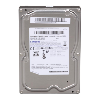
SpinPoint P80
Product Manual Rev. 01
16
4.3.3 Ventilation
SpinPoint P80 hard disk drives are designed to operate without the need of a cooling fan, provided the
ambient air temperature does not exceed 55ºC. Any user-designed cabinet must provide adequate air
circulation to prevent exceeding the maximum temperature.
4.4 Cable Connectors
The Interface/Power connector consists of three portions; a DC power connector, a configuration jumper
block, and the standard 40 pin AT-Bus Interface connector.
4.4.1 DC Power Connector
The DC power connector is mounted on the back edge of the Printed Circuit Board (PCB)
(Figure 4-4). Table 4-1 lists the pin assignments.
Table 4-1 Power Connector Pin Assignment
Pin Number Power Line Designation
1 +12V DC
2 +12V Return (Ground)
3 +5V Return (Ground)
4 +5V DC
4.4.2 AT-Bus Interface Connector
The AT-Bus interface connector on the drive connects the drive to an adapter or an on-board AT adapter in
the computer. JHST is a 40-pin Universal Header with two rows of 20 pins on 100-mil centers, as shown in
Figure 4-4.
To prevent the incorrect installation of the I/F cable, the connector has been keyed by the removal of Pin #20.
The connecting cable is a 40-conductor or a 80-conductor flat ribbon cable, and the maximum cable length is
0.46m (18 inches).
For pin assignments and signal descriptions, see Chapter 6, AT Interface and ATA Commands.
 Loading...