Do you have a question about the Samsung WA40J3000 and is the answer not in the manual?
Ensure errors are checked before entering test mode to avoid data loss.
Procedure to enter the diagnostic test mode by pressing specific buttons.
Instructions for activating and deactivating the Child Lock feature.
Understanding how error codes are indicated through blinking LEDs.
Details on various error codes and their associated symptoms.
Solution for units that operate continuously, often requiring PCB replacement.
Explanation of the ATC system for maintaining optimal wash temperatures.
Procedures for checking and resolving water level sensor issues.
Steps to diagnose and repair washing motor defects.
Troubleshooting water supply valve and drain pump malfunctions.
Resolving communication errors and door lock switch problems.
Diagnosing and fixing water leakage and unbalance code conditions.
Troubleshooting Mems PBA defects and overflow conditions.
Addressing temperature sensor faults and switch code issues.
Detailed pinout information for main and sub PCBs.
Diagrams of the SMPS module and associated connectors.
Visual representation of internal wiring and component connections.
Detailed pin assignments for various connectors and wire colors.
This document provides fast track troubleshooting information for the Samsung WA40J3000 washing machine, intended for use by experienced technicians.
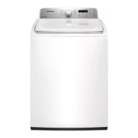
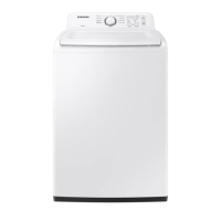
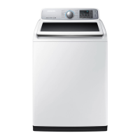
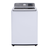
The Samsung WA40J3000 is a top-loading washing machine designed to clean clothes using various wash cycles and water temperature settings. It incorporates an Auto Temperature Control (ATC) function that utilizes a thermistor to maintain optimal wash temperatures for different cycles, ensuring effective cleaning performance while adhering to energy usage regulations. The machine features a control panel with a jog-dial for cycle selection, buttons for temperature, load size, and start/pause, and LED indicators for status and error codes.
While specific detailed technical specifications like motor power or drum capacity are not explicitly listed, the document provides insights into the machine's internal components and their functionalities: