10 S&C Instruction Sheet 761-515
Installation
Step 1
Remove the switch poles from their crates and
arrange them on the ground in the same order
in which they will be mounted on the structure.
When applicable, arrange the outboard bearing
assembly or assemblies in the same manner.
Protect the switch poles and bearings
from contamination by dirt, mud, oil, etc. If
necessary, use blocks to keep the bearings off
of the ground.
Attaching Couplings to the
Switch Poles
Step 2
NOTICE
There is an adjustable pipe coupling for each
section of interphase pipe. These adjustable
couplings are attached to the center switch
pole except for triangular-upright and tiered-
upright switch mounting configurations. See
Figure 4.
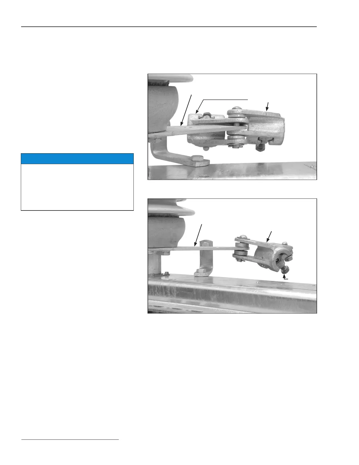
Attach pipe couplings to the operating lever of
each switch pole. Each pipe coupling includes
a 3/8-inch spacer, which is used if only one
coupling is attached to the operating lever. If
two couplings are required, the spacer can be
discarded. See Figures 2 and 3.
Operating lever
Pipe coupling
Figure 2. Assemble the pipe coupling to the operating lever—interphase
pipe on both sides of operating lever.
Operating lever
Pipe coupling
Set screw
Figure 3. Assemble the pipe coupling to the operating lever—interphase
pipe on one side of operating lever.
 Loading...


