26 S&C Instruction Sheet 761-515
Installation
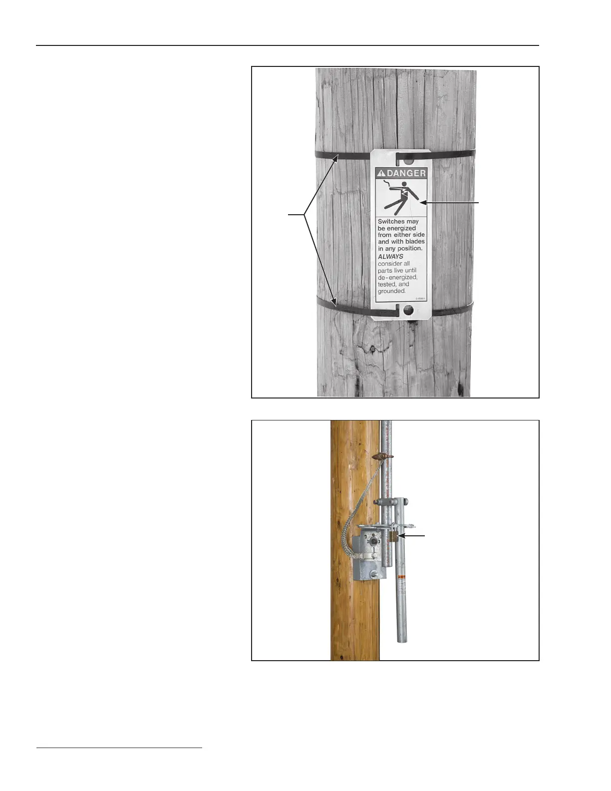
Step 29
Attach the danger label to the pole or structure
using two straps or bolts (user-furnished). See
Figure 27.
Position the danger label within three feet
of the switch pole-units and in full view of line
crews when viewed from the front of the switch.
For switches that mount on two poles, attach
another danger label to the second pole in the
same manner.
Connecting High-Voltage
Conductors
When high-voltage conductors are to be
connected using aluminum-alloy body connec-
tors
use the following procedures:
(a) Thoroughly wire-brush the current-
transfer surfaces of each connector, and
immediately apply a liberal coating of
Penetrox® A (available from Burndy
Corporation) or another suitable alumi-
num connector compound to the
brushed surfaces.
(b) Wire-brush each terminal pad of the in-
terrupter switch, and apply a coating of
Penetrox A. Bolt the connectors to the
terminal pads.
(c) Prepare the conductors using estab-
lished procedures, and clamp them in
their respective connectors.
Mass anode type connectors, such as the Catalog
Number 5300 series offered by S&C, that have been
designated by the connector manufacturer as being
suitable for direct attachment to copper-bearing alloy ter-
minal pads.
Straps
(by others)
Danger label
Figure 27. Attach the danger label to the pole or structure.
Padlock
Figure 28. Remove the padlock from the manual operating handle.
 Loading...


