S&C Instruction Sheet 761-515 23
Installation
To adjust the closed stop-plate:
(a) Loosen the hardware securing the
closed stop-plate. See Figure 22 on
page22.
(b) The stop plate holes are slotted to allow
room for adjustment. Position the
operating handle in the stop plate and
turn the operating handle as far as it will
go in the Closed position. (Counter
clockwise is standard on switches using
the rotating operating mechanism.) The
handle should be tight against the edge
of the stop plate, as shown in Figure 23
on page 22. Mark the position of the
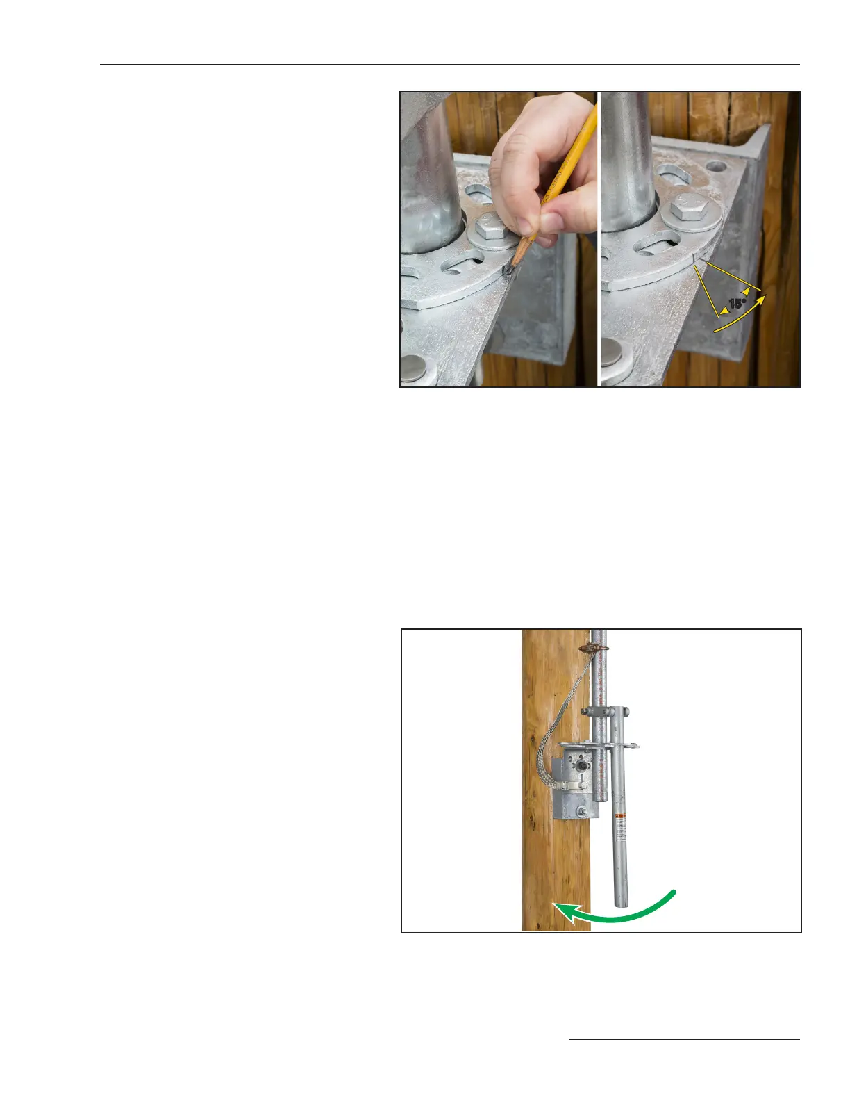
closed stop-plate. See Figure 24 (left).
(c) Lift the handle out of the way, and rotate
the stop plate an additional 15 degrees
counter-clockwise from the mark. See
Figure 24 (right). Make sure the open
stop plate lines up with the mark made
in Step 24. Tighten the stop plate hard-
ware to 40 ft-lbs.
(d) Push the handle into the closed stop
position. It should take signicant force
to secure the handle into the closed
stop. The handle will be rmly pressed
against the left side of the closed stop
plate. This pressure will hold the torque
in the pipe, creating the desired windup.
Move the handle into the Open position
to verify it ts into the open stop-plate.
See Figure 25.
Step 26
Recheck to be sure all clamp bolts and piercing
set screws have been torqued to final tightness.
Figure 25. Verify the wind up.
Figure 24. Mark across the open and closed stop plate. Rotate the closed
stop plate CCW approximately 15 degrees, and then re-align the open stop
plate with the mark made previously. Tighten the hardware.
15°
 Loading...


