12 S&C Instruction Sheet 761-545
Installation
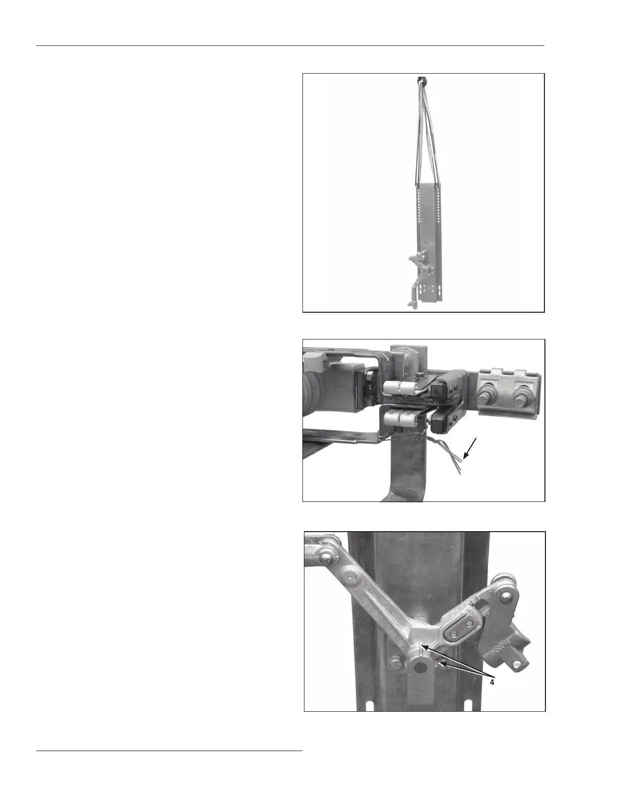
STEP 6. Hoist the bell-crank assembly, including base or
bracket, and bolt it into position as shown on the
erection drawing. See Figure 8.
STEP 7. To minimize time-consuming nal adjustments
make sure the switch is fully closed. Tie the
switch blades to their stationary main contacts.
See Figure 9.
STEP 8. Make sure the bell-crank is held in the 45-degree
position. The bell-crank and bell-crank bearing
have indexing ridges to facilitate alignment.
See Figure 10.
Figure 8. Hoisting the bell-crank into position.
Tie
Figure 9. Tieing the switch blade to the main contacts.
Figure 10. A bell-crank in the 45-degree position.
45-degree
position
marks
 Loading...


