14 S&C Instruction Sheet 761-545
Installation
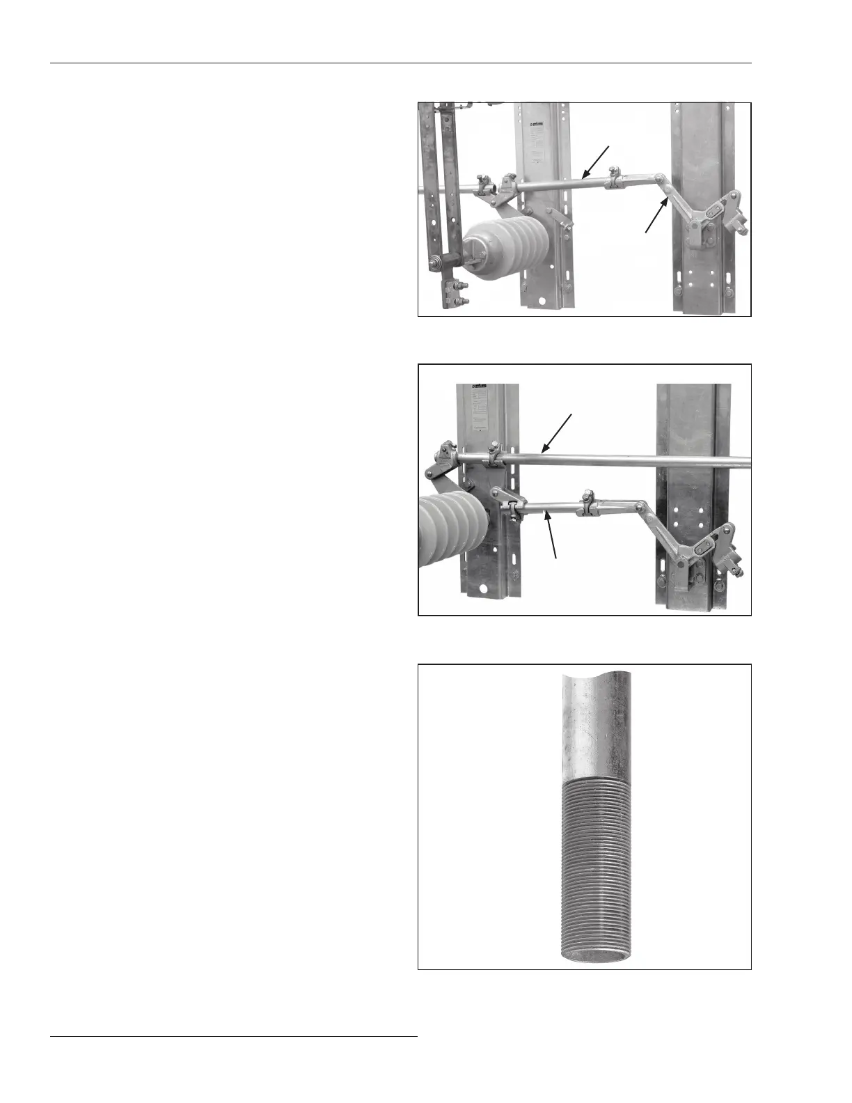
STEP 12. If the bell-crank assembly is mounted
outboard of the switch poles: Install the pipe
section connecting the driven arm of the bell-
crank to the nearest switch pole. See Figure 13.
Follow the directions in the “Installing Pipe
Couplings with Piercing Set Screws” section on
page 13.
Torque the clamp bolt of each pipe-coupling
clamp to final tightness, and continue turning
until a firm resistance is felt.
If the bell-crank assembly is mounted
between switch poles: Connect the drag link
to the interphase pipe using the offset coupling
previously attached to the drag link in Step 4
on page 11. See Figure 14. Follow the direction
in the “Installing Pipe Couplings with Piercing
Set Screws” section on page 13.
Torque the clamp bolt of each pipe-coupling
clamp to final tightness, and continue turning
until a firm resistance is felt.
Installing the Vertical Operating Pipe
S&C recommends making up each coupling connection as
work progresses from the top down.
STEP 13. One of the pipe sections furnished is threaded at
one end to accommodate the operating-handle
assembly. See Figure 15. Install this section of
pipe last, with the threads at the lower end.
If only one vertical operating-pipe section is
required, proceed to Step 16 on page 15.
Note: Do not tighten the piercing set screw
at the top of the lowest section of vertical
operating pipe until satisfactory operating-
handle adjustment is attained.
Driven arm of
bell-crank
Connecting
pipe
Figure 13. Pipe connecting the bell-crank.
Figure 15. A threaded vertical operating pipe.
Interphase pipe
Drag link
Figure 14. Connecting the drag link to the interphase pipe.
 Loading...


