S&C Instruction Sheet 761-545 15
Installation
STEP 14. Mount the rod guide(s) with the arm upward on
the pole or structure in accordance with the
dimension shown on the erection drawing. See
Figure 16. A positioning stud is furnished which
holds the rod guide arm at 45 degrees. When an
adjustable rod guide is included (for the tiered-
outboard switch mounting conguration only),
it should be mounted nearest the switch.
STEP 15. Install the upper section of operating pipe
between the bell crank and the uppermost rod
guide with the rod guide arm pointing upward
at a 45-degree angle. See Figure 17. Follow the
directions in “Installing Pipe Couplings with
Piercing Set Screws” section on page 13.
If more than one rod guide is used, install
vertical operating-pipe sections between the
rod guides in the same manner.
Installing the Operating Handle●
STEP 16. Mount the operating handle as shown on the
erection drawing. At the same time, use one of
the operating handle mounting bolts to attach
one end of the grounding strap (the end with the
grounding connector attached) to the handle
mounting plate. See Figure 18.
■
●
If suffix “-S8” or “-S9” is specified, refer instead to S&C Instruction
Sheet 769-510, “S&C Switch Operators - Type AS-10.” If suffix “-S16” is
specified, refer instead to S&C Instruction Sheet 1045M-510, “6801M
Automatic Switch Operators, Reciprocating and Rotating Switch Opera-
tion: Installation.”
■ The grounding recommendations described in this document may
differ from the standard operating and safety procedures of certain
electric utility companies. Where a discrepancy exists, the operating
procedures of the electric utility apply.
Figure 16. Attaching the rod guide.
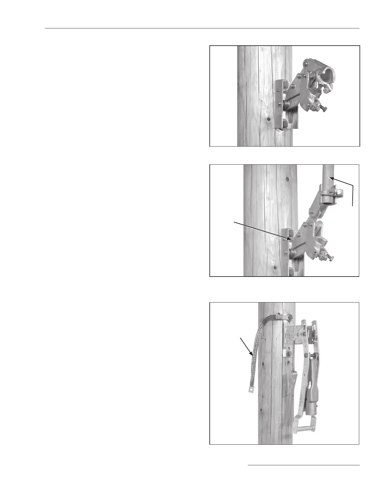
Figure 17. Installing the upper operating pipe section into
the rod guide.
Positioning
stud
Uppermost
section of
vertical
operating
pipe
Figure 18. Mounting the operating handle.
Grounding
strap
 Loading...


