S&C Instruction Sheet 761-545 13
Installation
Installing Pipe Couplings with Piercing Set
Screws
WARNING
Failure to properly install pipe couplings with piercing
set screws can cause slippage of operating pipe,
resulting in improper operation of the switch, arcing,
equipment damage, or electrical shock.
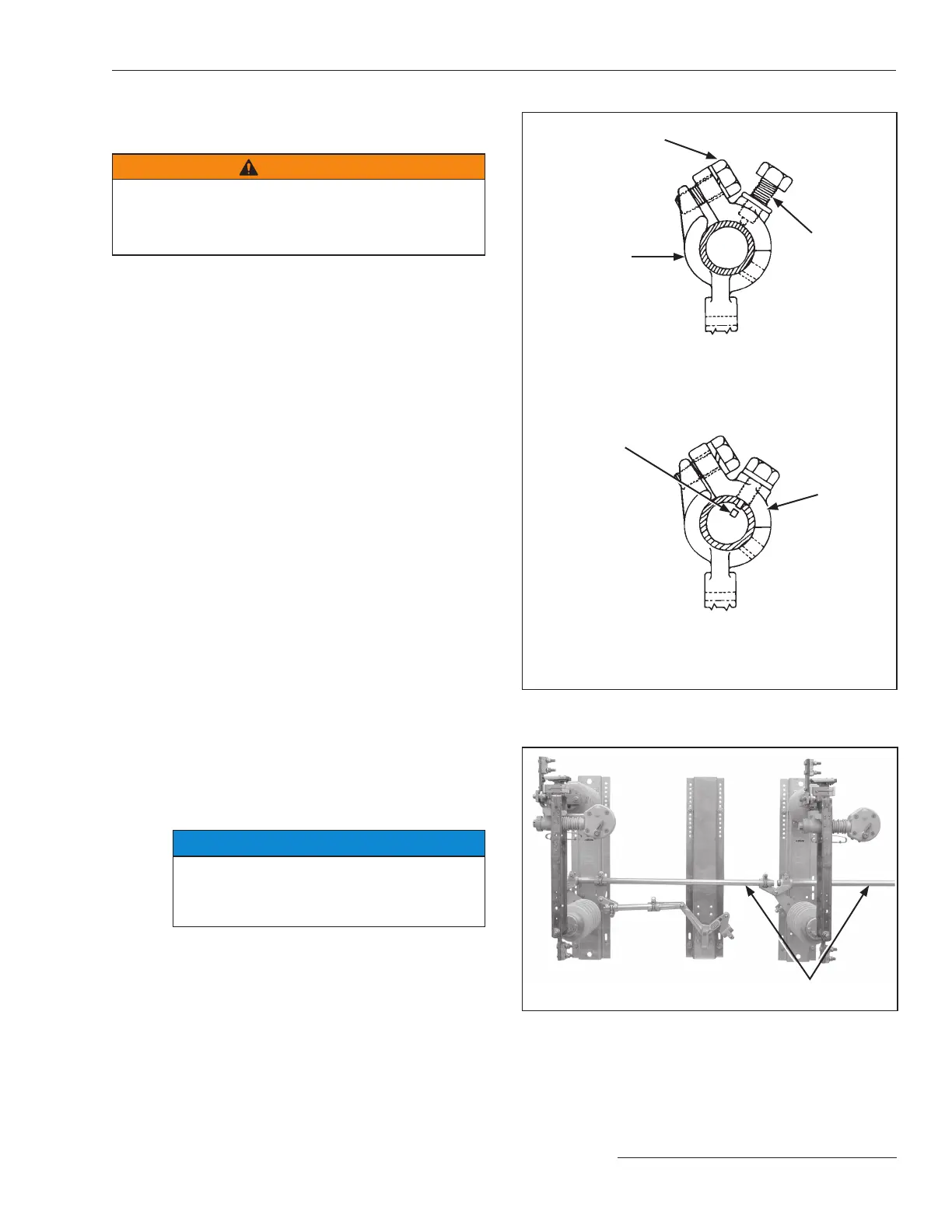
STEP 9. To properly install piercing set screws:
(a) Make sure the cutting tip of the piercing set
screw does not protrude through the body of
the clamp.
(b) Insert the operating pipe section into the
coupling and nger-tighten the clamp bolt(s).
(c) Adjust the operating pipe to the correct
length. Then, tighten the clamp bolt(s) to
nal tightness.
(d) Tighten the piercing set screw, piercing the
pipe, and continue turning until a rm
resistance is felt.
(e) Make sure the clamp bolt(s) are tight. See
Figure 11.
Installing the Interphase Pipe
STEP 10. Install the horizontal pipe sections connecting
the switch poles and the bell-crank assembly.
See Figure 12. Follow the directions in the
“Installing Pipe Couplings with Piercing Set
Screws” section.
Torque the clamp bolt of each pipe-coupling
clamp to final tightness, but do not tighten the
associated set screw until the mechanism has
been adjusted to attain full closure of all three
poles.
STEP 11. Make sure the bell-crank is held in the 45-degree
position. The bell-crank and bell-crank bearing
have indexing ridges to facilitate this alignment.
See Figure 10 on page 12.
NOTICE
The bell-crank arms should be within 5 degrees
of the 45-degree position for the most favorable
mechanical advantage when the switch is in
both the Open and Closed positions.
Figure 12. Pipe connecting the switch poles.
Interphase pipe sections
Figure 11. Installing the pipe couplings.
Piercing set screw in the shipping position (cutting
tip does not pro trude through the body of the clamp)
Operating pipe installed, clamp bolt fully tightened, and
piercing set screw in final position
Clamp bolt
Clamp
Coupling body
Piercing
set screw
Slug pierced
from pipe
 Loading...


